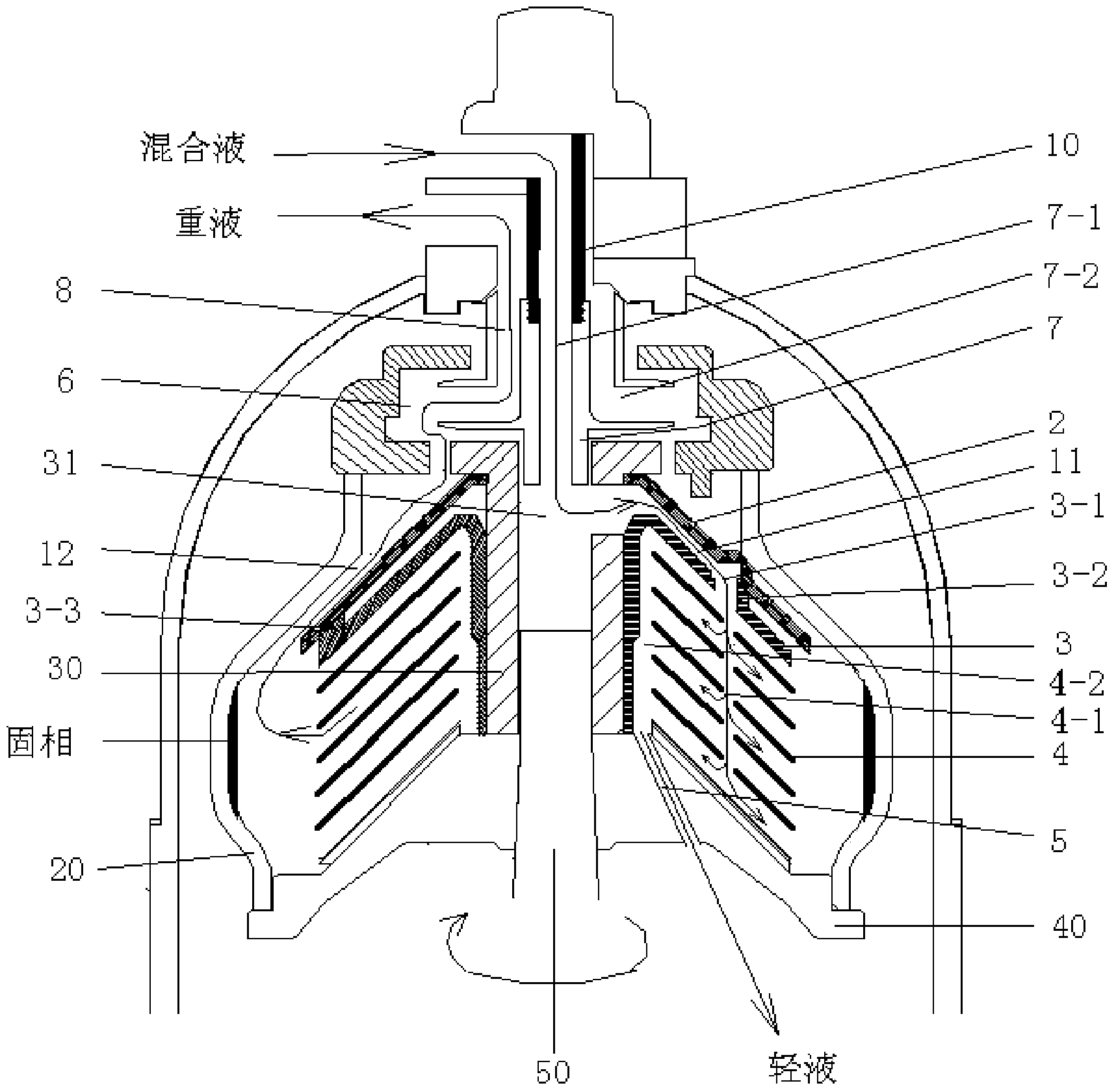
Internal runner structure of butterfly type centrifuge
A butterfly centrifuge and flow channel technology, applied in the field of centrifuges, can solve the problems of slow relative speed, affecting separation effect, slow discharge speed, etc.
- Summary
- Abstract
- Description
- Claims
- Application Information
AI Technical Summary
Problems solved by technology
Method used
Image
Examples
Embodiment Construction
[0025] The present invention will be further described below in conjunction with the accompanying drawings and specific embodiments.
[0026] figure 1 It is a structural schematic diagram of the inner channel structure of the butterfly centrifuge of the present invention.
[0027] Such as figure 1 As shown, the internal channel structure of the butterfly centrifuge includes: feeding pipe 10, centrifugal drum 20, mandrel 30, chassis 40, centripetal pump 7, several discs 4 in the separation area, light liquid discharge pipe 5, Heavy liquid discharge pipe 8, top disc 2, feed distribution disc 3, heavy liquid export maze 6, main shaft 50 and mandrel chamber 31.
[0028] The main shaft 50 is the central axis of the butterfly centrifuge. The mandrel 30 is fixed on the main shaft 50 , and the space in the center hole of the mandrel is the mandrel chamber 31 .
[0029] The main shaft 50 is driven by the motor through the transmission device to rotate at a high speed, thereby dri...
PUM
 Abstract
Description
Claims
Application Information
 - R&D
- Intellectual Property
- Life Sciences
- Materials
- Tech Scout
- Unparalleled Data Quality
- Higher Quality Content
- 60% Fewer Hallucinations
Browse by: Latest US Patents, China's latest patents, Technical Efficacy Thesaurus, Application Domain, Technology Topic, Popular Technical Reports.
© 2025 PatSnap. All rights reserved.Legal|Privacy policy|Modern Slavery Act Transparency Statement|Sitemap|About US| Contact US: help@patsnap.com


