
Intelligent LED lamp and intelligent LED lamp control system

A technology for control systems and lamps, applied in the field of lighting, can solve the problems of radiation pollution, hindering the popularization of LED energy-saving lamps, and weak ability to penetrate walls.

Inactive Publication Date: 2015-02-04
RCG OPTOELECTRONICS
View PDF3 Cites 27 Cited by
  • Summary
  • Abstract
  • Description
  • Claims
  • Application Information

AI Technical Summary

Problems solved by technology

Bluetooth control is limited to a small area, unable to achieve networked remote control
Zigbee technology mainly uses the 2.5G frequency exposure in the ISM frequency band, which has weak diffraction ability and weak wall penetration ability. Some manufacturers amplify the 2.5G signal, but this will cause additional radiation pollution, and it is also in line with Zigbee's low power consumption and energy saving contrary to the original intention
Wi-Fi control requires the user to bind the router provided by the manufacturer, which cannot solve the compatibility problem and reduces the usability of the product. Moreover, the router provided by the manufacturer is not open source code, the source code is encrypted and closed, the product is opaque, and the user cannot Obtaining setting permissions has greatly hindered the popularization of LED energy-saving lamps

Method used


Image

  • Intelligent LED lamp and intelligent LED lamp control system
  • Intelligent LED lamp and intelligent LED lamp control system
  • Intelligent LED lamp and intelligent LED lamp control system

Examples


Embodiment Construction

[0024] In order to make the object, technical solution and advantages of the present invention clearer, the present invention will be further described in detail below in conjunction with the accompanying drawings and embodiments.

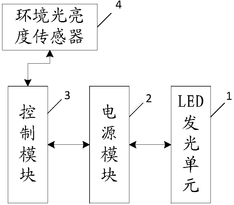
[0025] figure 1 It is a schematic diagram of an LED smart lamp provided by an embodiment of the present invention. according to figure 1 As shown, the LED smart lamp includes an LED lighting unit 1 , a power module 2 and a control module 3 . The control module 3 is connected with the power module 2 , and the power module 2 is connected with the LED lighting unit 1 . The control module 3 is used to receive the lamp control command sent by the control terminal, and send the lamp control command to the power module 2, and at the same time, send out the working status information of the LED intelligent lamp. The power module 2 is used to adjust the working state of the LED intelligent lamp according to the lamp control command. A Wi-Fi module can b...


PUM


Abstract

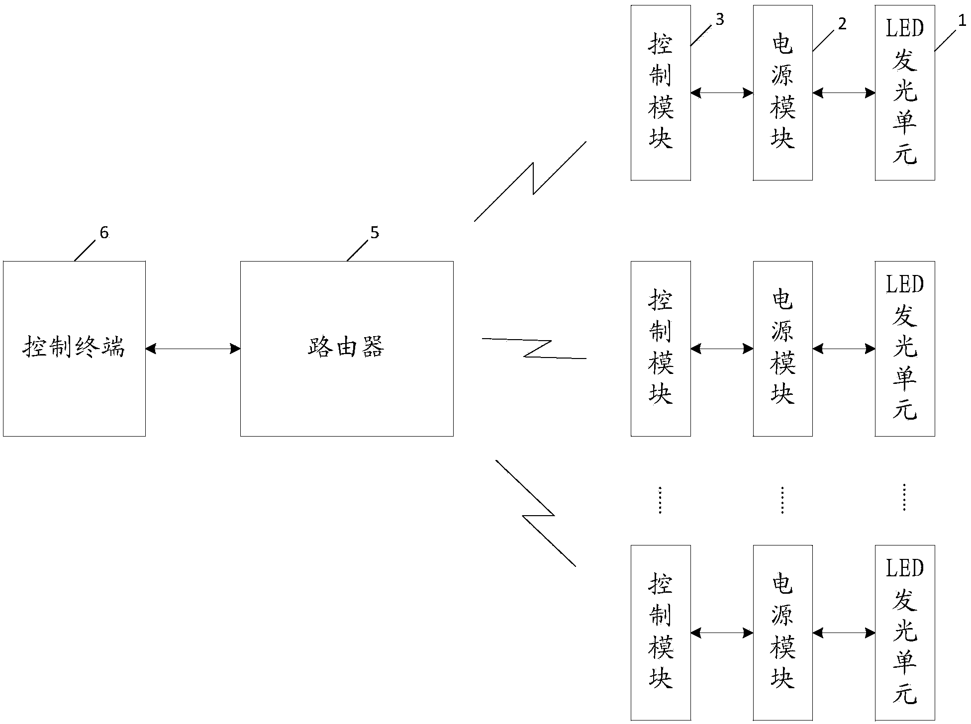
The invention relates to an intelligent LED lamp and an intelligent LED lamp control system. The intelligent LED lamp comprises an LED light emitting unit, a power source module and a control module, wherein the control module is connected with the power source module, the power source module is connected with the LED light emitting unit, the control module is used for receiving lamp control commands transmitted through a control terminal, and the lamp control commands are transmitted to the power source module. Meanwhile, information of the operating state of the intelligent LED lamp is transmitted. The power source module is used for adjusting the operating state of the intelligent LED lamp according to the lamp control commands. The intelligent LEDS lamp control system comprises intelligent LED lamps and the control terminal. The control terminal is used for transmitting the lamp control commands to the intelligent LED lamps via Wi-Fi or the internet and receiving the information of the operating states of the intelligent LED lamps. The control module and the power source module can be integrated within the intelligent LED lamp, and users can monitor the intelligent LED lamps via the control terminal.

Description

technical field [0001] The invention relates to the field of lighting technology, in particular to an LED intelligent lamp and a control system for the LED intelligent lamp. Background technique [0002] Existing LED lamps have control methods such as Bluetooth control, zigbee protocol-based control, and Wi-Fi control. Bluetooth control is limited to a small area, and cannot realize networked remote control. Zigbee technology mainly uses the 2.5G frequency exposure in the ISM frequency band, which has weak diffraction ability and weak wall penetration ability. Some manufacturers amplify the 2.5G signal, but this will cause additional radiation pollution, and it is also in line with Zigbee's low power consumption and energy saving Contrary to the original intention. Wi-Fi control requires the user to bind the router provided by the manufacturer, which cannot solve the compatibility problem and reduces the usability of the product. Moreover, the router provided by the manufa...

Claims


Application Information

Patent Timeline
Patent Type & Authority Applications(China)
IPC IPC(8): H05B37/02
CPCY02B20/40
Inventor 孟庆晨钟丽
Owner RCG OPTOELECTRONICS
Learn More