Solar energy equipment

A solar energy and equipment technology, applied in the integration of renewable energy, photovoltaic power generation, photovoltaic modules, etc., can solve problems such as lightning strikes, and achieve the effect of improving the service life and the best lightning protection effect.

Inactive Publication Date: 2015-02-04
AU OPTRONICS CORP
View PDF5 Cites 1 Cited by
  • Summary
  • Abstract
  • Description
  • Claims
  • Application Information

AI Technical Summary

Problems solved by technology

[0004] The purpose of the present invention is to provide a kind of solar energy equipment, which is used to solve the problem of the risk of being struck by lightning when the solar module is installed in a building without a lightning rod

Method used


Image

  • Solar energy equipment
  • Solar energy equipment
  • Solar energy equipment

Examples


Embodiment Construction

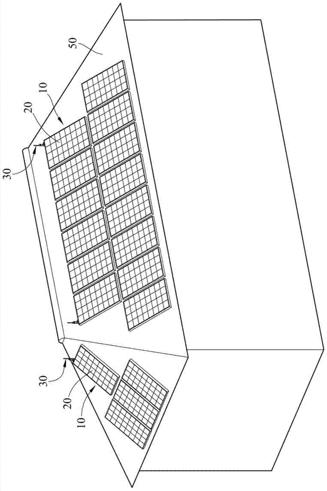
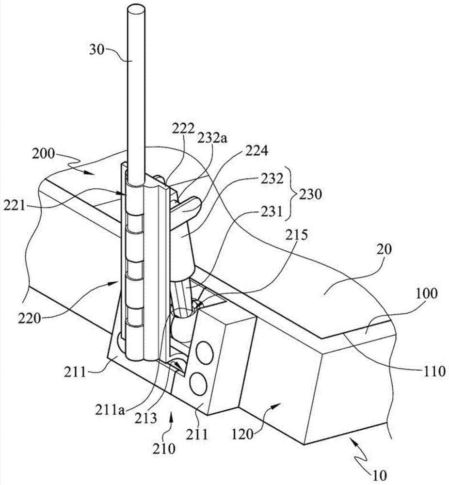
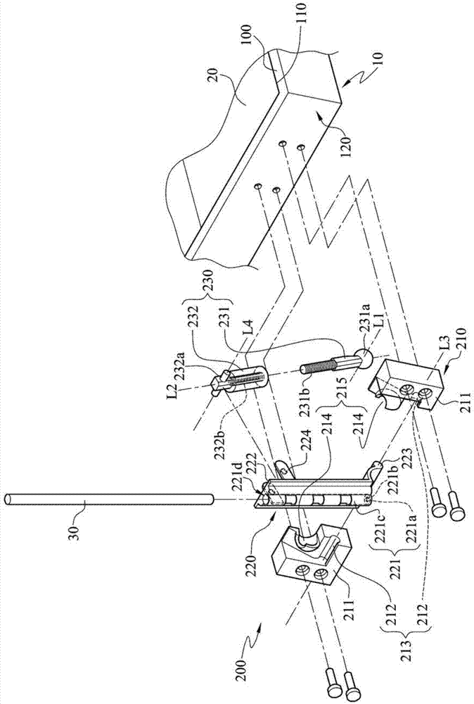
[0057] see Figure 1 to Figure 5 . figure 1 It is a three-dimensional schematic diagram of the solar equipment combined with the solar module disclosed in the first embodiment installed on the roof. figure 2 for figure 1 A partial perspective view of a solar device combined with a solar module. image 3 for figure 2 The decomposition diagram. Figure 4 for figure 2 top view diagram. Figure 5 for Figure 4 Schematic sectional view drawn along section line 5-5.

[0058] Such as figure 1 and figure 2 As shown, the solar device 10 of this embodiment includes a frame 100 , a lightning rod carrying module 200 and a lightning rod module 30 . The solar energy device 10 of this embodiment can be selectively placed on the highest point of the roof 50 or the opposite ends of the top of the roof 50 in actual installation, so as to obtain the best lightning protection effect with the least number of lightning rod modules 30 .

[0059] The frame 100 has a mounting slot 110 f...


PUM


Abstract

The invention discloses solar energy equipment comprising a framework and a lightning rod bearing module. The lightning rod bearing module comprises a seat body and an insulating bearing tube. The seat body is positioned on the framework, the insulating bearing tube is provided with a lightning rod bearing groove, and the insulating bearing tube is pivoted on the seat body.

Description

technical field [0001] The invention relates to a frame module, in particular to a solar device. Background technique [0002] In recent years, the creation of a green living environment is the goal advocated by all countries. In a highly civilized world, due to the impact of human activities, carbon dioxide will be emitted from various vehicles that generate power by burning oil, making carbon dioxide in the air The content of the content is constantly increasing, and the greenhouse effect is becoming more and more serious, as well as the phenomenon of global warming. Therefore, countries are constantly actively developing alternative energy sources that can replace petroleum, and general alternative energy sources can be mainly divided into biomass energy, wind power or solar energy. Power generation, among which solar power generation has attracted the most attention. Since solar energy itself does not cause pollution, energy exhaustion, and is easy to obtain, solar energ...

Claims


Application Information

Patent Timeline
Patent Type & Authority Applications(China)
IPC IPC(8): H02S30/00H01T19/04
CPCH01T19/04H02S30/00Y02B10/10Y02E10/50
Inventor 陈智勇苏子文
Owner AU OPTRONICS CORP
Why Eureka
Try Eureka