
High-frequency vacuum wood drying method and high-frequency vacuum wood drying equipment

A wood drying and vacuum technology, used in drying solid materials, lighting and heating equipment, local stirring dryers, etc. Effect

Active Publication Date: 2015-02-04
河北华氏纪元高频设备有限公司
View PDF6 Cites 13 Cited by
  • Summary
  • Abstract
  • Description
  • Claims
  • Application Information

AI Technical Summary

Problems solved by technology

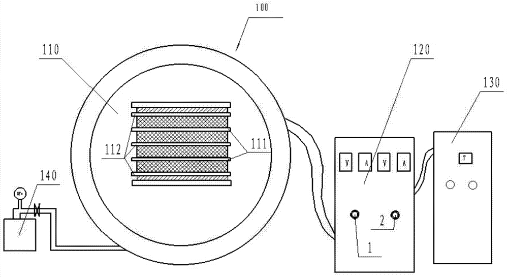
[0003] First, by manually observing the anode ammeter and the grid ammeter to turn the adjustment knobs 1 and 2, the adjustment amount cannot be accurately controlled, and overshoot and detuning are prone to occur, reducing the heating efficiency of wood, increasing loss, and even causing equipment damage.
[0004] Second, the minimum adjustment amount of the grid feedback coil is 1 turn, and it cannot be adjusted by half a turn or even smaller, so adjusting the oscillating current by changing the coil inductance has certain fluctuations and is prone to sparking
[0005] Third, because the wood moisture content changes in real time, it is necessary to manually observe and adjust the current in real time, otherwise the stability of the heating wood current cannot be guaranteed. unattended
[0006] Fourth, in order to prevent the high-frequency current in the high-frequency generator from affecting the detection of the anode current and grid current in the control cabinet, the vacuum wood drying device 100 in the prior art separates the high-frequency generator cabinet and the control cabinet, There are many connections among them, and the failure rate increases, resulting in waste of materials

Method used


Image

  • High-frequency vacuum wood drying method and high-frequency vacuum wood drying equipment
  • High-frequency vacuum wood drying method and high-frequency vacuum wood drying equipment
  • High-frequency vacuum wood drying method and high-frequency vacuum wood drying equipment

Examples


Embodiment Construction

[0020] In the following description, for purposes of explanation, numerous specific details are set forth in order to provide a thorough understanding of one or more embodiments. It may be evident, however, that these embodiments may be practiced without these specific details. In other instances, well-known structures and devices are shown in block diagram form in order to facilitate describing one or more embodiments.

[0021] Various embodiments according to the present invention will be described in detail below with reference to the accompanying drawings.

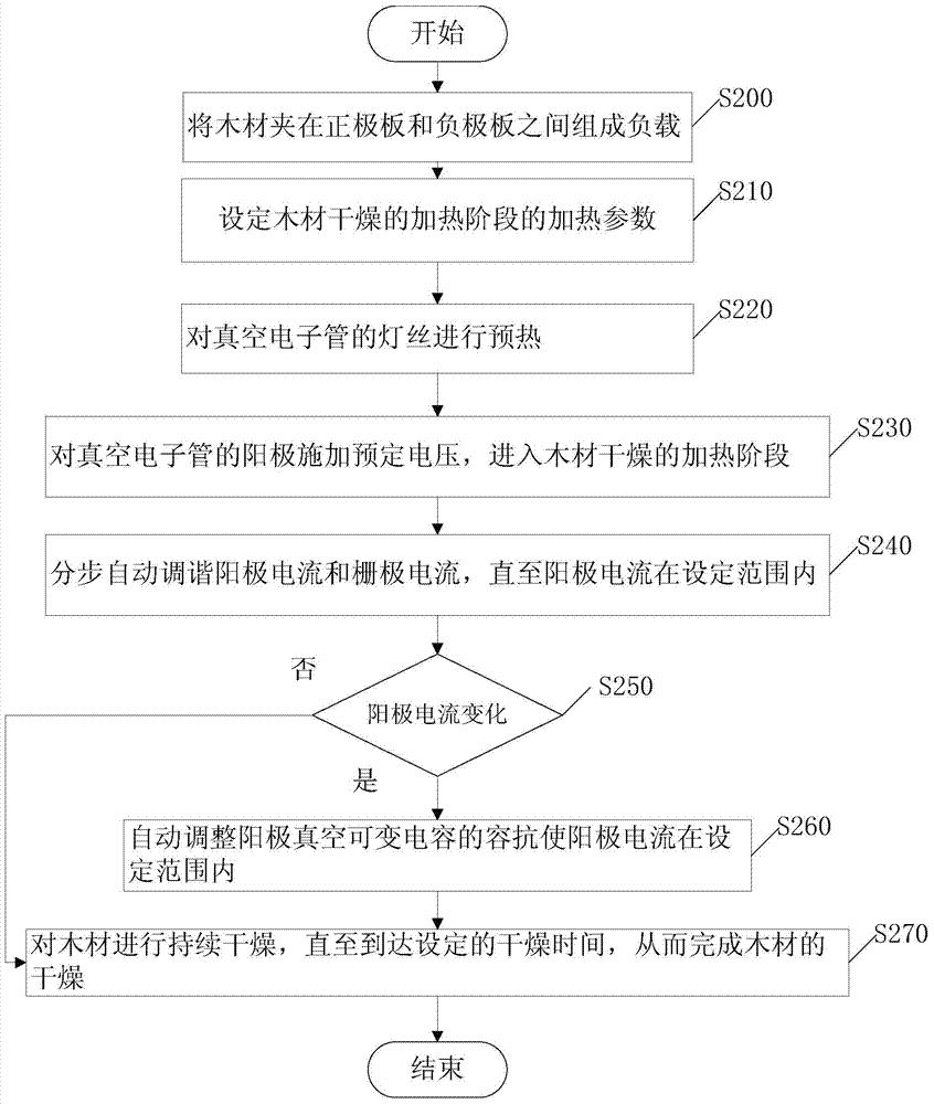
[0022] figure 2 It is a flow chart of the high-frequency vacuum wood drying method of the present invention. As shown in the figure, according to an embodiment of the present invention, a high-frequency vacuum wood drying method is provided, which includes the following steps:

[0023] First, in step S200, wood is sandwiched between the positive plate and the negative plate to form a load, the positive plate is conn...


PUM


Abstract

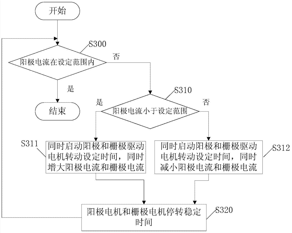
The invention provides a high-frequency vacuum wood drying method and high-frequency vacuum wood drying equipment. The drying method comprises the following steps that wood is clamped between a positive electrode plate and a negative electrode plate, heating parameters in the wood drying heating stage are set, an electron tube lamp filament is preheated, positive voltage is exerted onto an electron tube anode, the process starts to enter the heating stage, anode current and grid electrode current are automatically turned step by step until the anode current reaches the set range, whether the anode current is changed or not is judged, if the anode current is changed, the anode vacuum variable capacitor is automatically regulated so that the anode current is maintained in the set range, if the anode current is not changed, the wood is continuously dried until the set drying time is reached, and the wood drying is completed. The anode to grid electrode ratio is maintained in the set range, the anode current and the grid electrode current are automatically regulated step by step, the regulation is precise, and the real unattended operation is realized.

Description

technical field [0001] The invention relates to the field of wood drying, more specifically, to a high-frequency vacuum wood drying method and equipment thereof. Background technique [0002] Existing high-frequency vacuum wood drying equipment 100 such as figure 1 As shown, it includes: a vacuum tank 110 for placing wood that needs to be dried, and each layer of wood is located between the positive heating electrode 111 and the negative heating electrode 112; a vacuum pump 140 is used for vacuuming the vacuum tank 110, and a vacuum is provided on it The meter is used to display the vacuum degree in the vacuum tank; the transformer, rectifier bridge, electron tube, inductance, capacitor and other components that generate high-frequency current are placed in the high-frequency generating cabinet 120 cabinets. Among them, the electron tube includes an anode, a grid and a cathode. The anode of the electron tube supplies current to the positive heating electrode 111, and the ca...

Claims


Application Information

Patent Timeline
IPC IPC(8): F26B7/00F26B9/06F26B23/08
Inventor 华平陈开洪李洪生
Owner 河北华氏纪元高频设备有限公司
Learn More