
Tide level self-adaption device of vibration floater wave power generation device

A power generation device and wave energy technology, which is applied in the direction of ocean energy power generation, hydropower generation, engine components, etc., can solve the problems of limit switch damage, strength reduction, structural deformation, etc., and achieve reduced manufacturing costs, low use and maintenance costs , simple structure and stable effect

Active Publication Date: 2015-02-04
OCEAN UNIV OF CHINA
View PDF9 Cites 19 Cited by
  • Summary
  • Abstract
  • Description
  • Claims
  • Application Information

AI Technical Summary

Problems solved by technology

However, the use of limit switches to monitor tide level changes has the following disadvantages: in marine environments, limit switches are mechanically susceptible to damage caused by extreme wave conditions, and are also prone to switch failure due to frequent mechanical contact; circuit failures are prone to occur in signal transmission And the signal fails, and the control system cannot distinguish the position change of the float due to the change of the tide level or the action of the large wave, and it is easy to issue wrong instructions and cause misoperation
However, the use of liquid level gauges to monitor changes in tidal levels has the following disadvantages: Since the tide well needs to be installed on the wave energy power generation device, the overall structure of the device becomes complicated and the strength decreases, and the structure is prone to deformation or even damage; if the tide well is blocked , will directly affect the liquid level gauge’s monitoring of external tide level changes, making the screw jack unable to perform correct actions; the junction box on the top of the liquid level gauge needs to be waterproofed and sealed, and if the line is damp or flooded, it will directly affect the working performance of the liquid level gauge Even cause the liquid level gauge to fail

Method used


Image

  • Tide level self-adaption device of vibration floater wave power generation device

Examples


Embodiment Construction

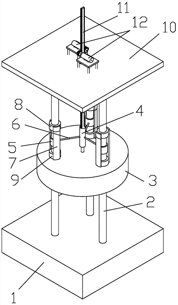
[0021] The tidal level adaptive device of the oscillating buoy wave energy generating device of the present invention, such as figure 1 As shown, the oscillating buoy wave energy generating device includes a submersible buoy 1, a guide rod 2, a float 3, a hydraulic cylinder 4, and a sleeve 5. The guide rod 2 is installed on the submersible buoy 1, and both the float 3 and the sleeve 5 are set on the guide rod. 2, the cylinder body of the hydraulic cylinder 4 is fixedly connected to the sleeve 5 through the support arm 6, and the piston rod of the hydraulic cylinder 4 is fixedly connected to the float 3.

[0022] The tide level adaptive device includes a wave height adjustment frame and a damping mechanism.

[0023] The wave height adjustment frame is fixed on the float 3, including the connection plate 7 and the upper limit sleeve 8 and the lower limit sleeve 9 fixed on the connection plate 7, and the upper limit sleeve 8 and the lower limit sleeve 9 are all set on the guide r...


PUM


Abstract

The invention discloses a tide level self-adaption device of a vibration floater wave power generation device. The vibration floater wave power generation device comprises a submerging and surfacing body, guide rods, a floater, a hydraulic cylinder and sleeves, wherein the guide rods are arranged on the submerging and surfacing body; the floater and the sleeves are both sleeved on the guide rods; the cylinder block of the hydraulic cylinder is fixedly connected with the sleeves through support arms; a piston rod of the hydraulic cylinder is fixedly connected with the floater; the tide level self-adaption device comprises a wave height adjustment frame and a damping mechanism. According to the tide level self-adaption device, adaptive adjustment can be performed on the position of the hydraulic cylinder along with the tide level change, so that the effective working distance between the floater and the hydraulic cylinder is ensured, the power generation device is ensured to have higher energy conversion efficiency, and meanwhile, the dangerous situation that the piston rod rushes to the top or is separated from the cylinder block of the hydraulic cylinder is avoided; moreover, the tide level self-adaption device is formed completely by matching mechanical structures, and electronic components or electronic control systems are not related, so that the tide level self-adaption device is simpler and more stable in structure, and cannot be influenced by the marine environment, can stably work under the maritime severe environment for a long time, and does not need to be maintained frequently, so that the use and maintenance cost is extremely low.

Description

technical field [0001] The invention belongs to the technical field of an oscillating float type wave energy generating device, and in particular relates to a tide level self-adapting device of an oscillating float wave energy generating device. Background technique [0002] The oscillating buoy type wave energy generation device is generally used in nearshore and offshore sea areas. The underwater submerged floating body of the anchor chain anchors the device to form a floating structure. The relative motion absorbs the wave energy, which in turn converts the energy into electrical energy through mechanical or hydraulic conversion. [0003] In order to enable the device to obtain greater relative motion, tension anchors are generally used to anchor the underwater floating body and the overall structure of the device to form a relatively stable interface, and only the movable float on the water surface floats with the waves and tide levels. The movable float is connected to...

Claims


Application Information

Patent Timeline
IPC IPC(8): F03B13/22F03B11/00
CPCY02E10/20Y02E10/30
Inventor 史宏达曹飞飞刘臻曲娜赵环宇胡戈行韩治
Owner OCEAN UNIV OF CHINA
Learn More