This helps you quickly interpret patents by identifying the three key elements:
Problems solved by technology
Method used
Benefits of technology
Problems solved by technology
[0008] Aiming at the problems existing in the prior art that many equipments are needed, the system is complicated, the equipment maintenance is large, the cost is high, and the battery panels located at high places cannot be cleaned, the present invention provides a flying saucer type photovoltaic battery panel cleaner and its cleaning method
Method used
Image
Click on the blue label to locate the original text in one second.
Reading with bidirectional positioning of images and text.
Examples
Embodiment 1
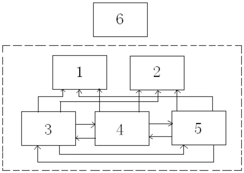
[0046] A kind of flying saucer type photovoltaic panel cleaner of the present invention, as figure 1 As shown, it includes a cleaning system 2 , a power supply system 3 and a control system 4 , and is characterized in that it also includes a flight system 1 , a communication system 5 and a remote control system 6 .
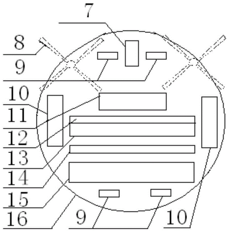
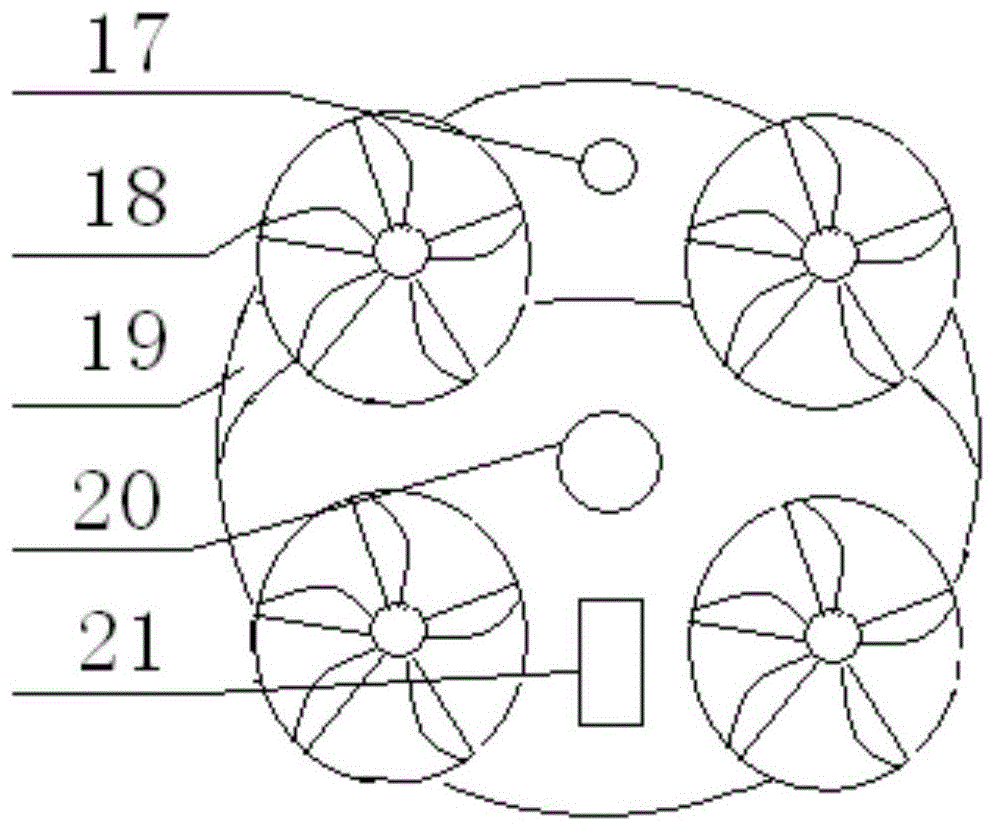
[0047] The flight system 1, the cleaning system 2, the power system 3, the control system 4 and the communication system 5 form a control and execution mechanism, that is, a washer host, and the washer host is a disc structure, also known as a disc structure. like figure 2 As shown, the cleaning system 2 is composed of two parts, one part is composed of the power supply system 3, the control system 4, the communication system 5 and the control system 4 arranged in the disc structure to form the power and control part; the other part is arranged in the cleaning system. Cleaning tools on the site of system 2, i.e. corner brush 8, squeegee 12, sweeping brush 13, du...
Embodiment 2
[0092] In this embodiment, a flying saucer-type photovoltaic cell panel cleaner is selected to remotely clean the five roof photovoltaic cell assemblies of the building where it is located. The cleaner can be released from any floor of the building.
[0093] The user uses the remote control to operate, the operation mode adopts the manual remote control flight mode with buttons and touch, and the operation mode combined with automatic cleaning, and sets the cleaning path from top to bottom, from left to right and cleaning for 2 minutes each by suction, sweeping and wiping Way. The specific operation is as follows:
[0094] (1) Press the second right button and the first right button of the automatic cleaning mode button 34 of the remote control, and the cleaner performs the automatic cleaning function and the automatic flight function to the next target;
[0095] (2) Press the start / stop flight button of the remote control button 29 and the return button by the original fligh...
PUM
Abstract
The invention discloses a flying saucer-type photovoltaic battery panel cleaner and a cleaning method thereof, which belong to the field of remote-controlled flight cleaning. A flying saucer type photovoltaic battery panel cleaner, which includes a cleaning system, a power supply system and a control system, a flight system, a communication system and a remote control system; The main unit of the washer and the remote control system constitute the remote control mechanism alone. The remote control system and the main unit of the washer send and receive signals through the wireless communication module built in the signal transceiver port. The path is set through the remote control system, and the control signal is transmitted. The target cleaning position is the photovoltaic cell module to be cleaned, and corresponding actions are performed to complete the process of sweeping, sucking or wiping. The utility model has the advantages of simple structure, convenient maintenance and low cost, and it is convenient to clean the solar photovoltaic battery panels located at a higher place.
Description
technical field [0001] The invention belongs to the field of remote cleaning, and in particular relates to a flying saucer type photovoltaic panel cleaner and a cleaning method thereof. Background technique [0002] With the development of new energy, solar photovoltaic power generation is also developing rapidly, and more and more solar power stations are being built. Large-scale solar photovoltaic power stations are usually built in places with high terrain and sufficient sunshine, but such places are windy and sandy, and water resources are scarce, so it is easy to accumulate dust, bird droppings, insect corpses and other organic and inorganic components on the solar panels pollutants. The data shows that the theoretical power generation efficiency of solar panels is 25%, but the actual power generation efficiency is 23%. After being polluted, the power generation efficiency drops to 17%-18%, and the power loss reaches 22%-30%. Therefore, the cleanliness of solar panels...
Claims
Application Information
Patent Timeline
Application Date:The date an application was filed.
Publication Date:The date a patent or application was officially published.
First Publication Date:The earliest publication date of a patent with the same application number.
Issue Date:Publication date of the patent grant document.
PCT Entry Date:The Entry date of PCT National Phase.
Estimated Expiry Date:The statutory expiry date of a patent right according to the Patent Law, and it is the longest term of protection that the patent right can achieve without the termination of the patent right due to other reasons(Term extension factor has been taken into account ).
Invalid Date:Actual expiry date is based on effective date or publication date of legal transaction data of invalid patent.