
A rotary barrel photocatalytic reaction device

A technology of photocatalytic reaction and rotating bucket, which is applied in chemical instruments and methods, chemical/physical processes, chemical/physical/physicochemical processes of energy application, etc. It can solve the problems of catalysts not being able to be renewed, dead angles of reaction devices, and utilization of light energy. Low-level problems, to achieve the effect of increasing light energy utilization and solving sealing problems

Inactive Publication Date: 2016-07-06
INNER MONGOLIA NORMAL UNIVERSITY
View PDF4 Cites 0 Cited by
  • Summary
  • Abstract
  • Description
  • Claims
  • Application Information

AI Technical Summary

Problems solved by technology

[0005] The drum-type photocatalytic reaction device of the present invention overcomes the shortcomings of the current photocatalytic device, and can solve the problems that the above-mentioned catalyst cannot be renewed, there are dead angles in the reaction device, and the light energy utilization rate is low.

Method used


Image

  • A rotary barrel photocatalytic reaction device
  • A rotary barrel photocatalytic reaction device
  • A rotary barrel photocatalytic reaction device

Examples


Embodiment Construction

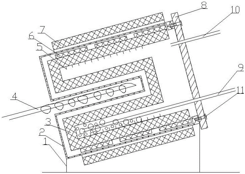
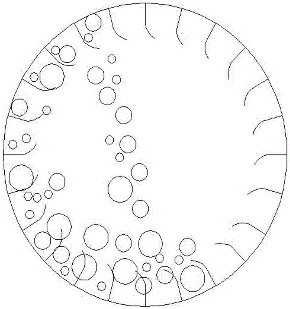
[0029] Such as Figure 1-4 As shown, the drum type photocatalytic reaction device provided by the present invention, the light contact area, according to Figure 4 It can be seen that the contact area between the catalyst and the light can be adjusted by adjusting the angle between the reactor and the ground. When the same amount of catalyst is loaded, the light area decreases as the inclination angle of the equipment increases.

[0030] The specific operation process is as follows,

[0031] 1) Open the sealing metal flange 8, load the catalyst, and tighten the screw 11.

[0032] 2) Turn on the motor, and the annular permanent magnet 7 drives the cylindrical inner cylinder 3 to rotate

[0033] 3) Open the gas inlet 9 to feed the reaction gas, and open the gas outlet 10 to keep the gas flowing.

[0034] 4) Turn on the light source 4, and the catalyst fully reacts with the reaction gas.

[0035] 5) After the reaction is finished, feed a certain amount of inert gas and all pr...


PUM


Abstract

The invention discloses a rotary drum type photo-catalytic reaction device. A metal reactor bracket is connected with an outer cylinder barrel; the outer cylinder barrel is supported by the metal reactor bracket; a certain included angle is formed between the outer cylinder barrel and the ground; an inner cylinder barrel is placed in the outer cylinder barrel; three uniform annular permanent magnets are mounted on the outer wall of the inner cylinder barrel and are matched with the outer cylinder barrel; a light source is inserted into the center of the outer cylinder barrel and is not in contact with the outer cylinder barrel; a shoveling plate is mounted on the inner wall of the inner cylinder barrel and is parallel to the light source; an annular permanent magnet is parallel to the three uniform annular permanent magnets and is mounted outside the outer cylinder barrel; the shoveling plate and the inner cylinder barrel rotate together, so that a catalyst can be updated; a sealing metal flange is mounted at the top of the outer cylinder barrel; a gas inlet and a gas outlet are symmetrically formed in the sealing metal flange and cannot rotate along with the inner cylinder barrel; screws are arranged at two ends of the sealing metal flange. The surface of the catalyst can be updated, and the problem of sealing caused by mechanical stirring is solved.

Description

technical field [0001] The invention relates to a photocatalytic experimental reaction device, which belongs to the field of photocatalytic instruments and devices. Background technique [0002] Since the discovery of photocatalyst by Professor Fujishima Akira of the University of Tokyo in 1967, photocatalysis has been gradually proposed. In 1972, Fujishi and others published "Electrochemical photolysis of water at semiconductor electrode" on Nature, which opened the prelude to a new era of photocatalysis. In the following decades, photocatalysis technology has received widespread attention. Photocatalysis is a substance that does not change itself under the irradiation of light, but can promote chemical reactions. In recent years, with the lack of energy and the aggravation of environmental pollution, the photocatalytic field is also constantly improving the requirements, so it is imperative to improve the utilization rate of the photocatalytic equipment for the catalyst. ...

Claims


Application Information

Patent Timeline
Patent Type & Authority Patents(China)
IPC IPC(8): B01J8/10
CPCB01J8/10B01J19/12B01J2208/00867B01J2208/00938B01J2219/0892B01J2219/12
Inventor 侯海元徐爱菊阿古拉萨嘎拉刘子忠照日格图
Owner INNER MONGOLIA NORMAL UNIVERSITY
Learn More