Torque tube stress intensity checking method for externally biased non-coaxial type cab stabilizer bar
A non-coaxial, stress-intensive technology, used in special data processing applications, instruments, electrical and digital data processing, etc., can solve the problems that cannot provide analytical calculation formula, can not meet the analytical design of cab stabilizer bar system and CAD software development. requirements, failure to provide the calculation method for checking the stress strength of twisted tubes, etc., to achieve the effect of speeding up product development, reducing design and test costs, and improving ride comfort and safety
- Summary
- Abstract
- Description
- Claims
- Application Information
AI Technical Summary
Problems solved by technology
Method used
Image
Examples
Embodiment 1
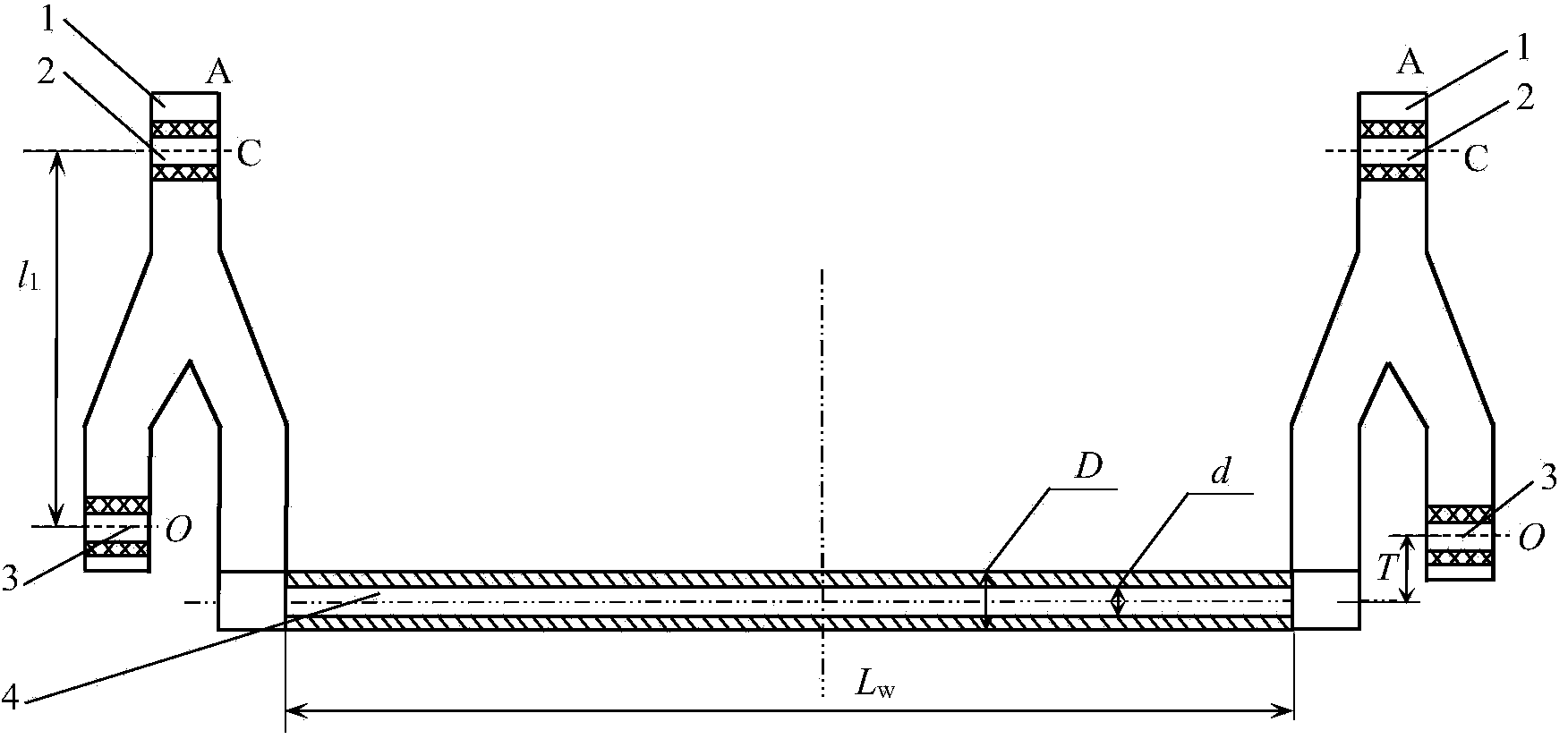
[0031] Example 1: The structure of an externally offset non-coaxial cab stabilizer bar system is symmetrical, as shown in figure 2 As shown, it includes: swing arm 1, suspension rubber bushing 2, torsion rubber bushing 3, torsion tube 4; wherein, the torsion tube 4 is not coaxial with the torsion rubber bushing 3, and the external offset of the torsion tube 4 is T =50mm; the length L of the torsion tube 4 w =1500mm, inner diameter d=46mm, outer diameter D=50mm, modulus of elasticity E=200GPa, Poisson’s ratio μ=0.3, allowable stress [σ]=500MPa; suspension rubber bushing 2 and torsion rubber bushing 3 The distance between them, that is, the length of the swing arm l 1 =380mm; the load F=5000N at the suspension installation position C of the swing arm. According to the structure and material characteristic parameters of the stabilizer bar given above, the torsion tube of the externally offset non-coaxial cab stabilizer bar is calculated and the strength is checked, and the str...
Embodiment 2
[0049] Embodiment 2: The structural form of an externally biased non-coaxial cab stabilizer bar system is the same as that of Embodiment 1, such as figure 2 As shown, wherein the torsion tube 4 is not coaxial with the torsion rubber bushing 3, the external offset T of the torsion tube 4 is 100mm; the length L of the torsion tube 4 w =1000mm, inner diameter d=45mm, outer diameter D=50mm, modulus of elasticity E=200GPa, Poisson’s ratio μ=0.3, allowable stress [σ]=500MPa; suspension rubber bushing 2 and torsion rubber bushing 3 The distance between, that is, the length of the swing arm l 1 =350mm; the load F=5000N at the suspension installation position C of the swing arm. According to the structure and material characteristic parameters of the stabilizer bar given above, the torsion tube of the externally offset non-coaxial cab stabilizer bar is calculated and the strength is checked, and the stress under the condition of load F=5000N Carry out ANSYS simulation verification. ...
PUM
| Property | Measurement | Unit |
|---|---|---|
| The inside diameter of | aaaaa | aaaaa |
| Outer diameter | aaaaa | aaaaa |
| Tube length | aaaaa | aaaaa |
Abstract
Description
Claims
Application Information
 - R&D Engineer
- R&D Manager
- IP Professional
- Industry Leading Data Capabilities
- Powerful AI technology
- Patent DNA Extraction
Browse by: Latest US Patents, China's latest patents, Technical Efficacy Thesaurus, Application Domain, Technology Topic, Popular Technical Reports.
© 2024 PatSnap. All rights reserved.Legal|Privacy policy|Modern Slavery Act Transparency Statement|Sitemap|About US| Contact US: help@patsnap.com


