
Method for adjusting reflectors through decentration measuring instrument

A mirror and partial measurement technology, which is applied in installation, instrumentation, optics, etc., can solve the problems of low pass rate, long lens assembly and adjustment cycle, and difficult to guarantee the center deviation of lens group, etc., and achieve the effect of improving the efficiency of assembly and adjustment

Inactive Publication Date: 2015-01-28
YUNNAN KIRO CH PHOTONICS
View PDF7 Cites 17 Cited by
  • Summary
  • Abstract
  • Description
  • Claims
  • Application Information

AI Technical Summary

Problems solved by technology

[0005] The purpose of the present invention is to solve the problem that it is difficult to ensure the center deviation of each lens group during the assembly and adjustment process of high-precision catadioptric optical lenses using autocollimators, lasers and other equipment, the center position cannot be monitored in real time, and the lens assembly and adjustment cycle is long. , the deficiency of low pass rate, provide a method for installing and adjusting the center deviation measuring instrument that can monitor the center position of each lens of the high-precision catadioptric optical lens in real time, and easily adjust the angle of the mirror

Method used


Image

  • Method for adjusting reflectors through decentration measuring instrument
  • Method for adjusting reflectors through decentration measuring instrument
  • Method for adjusting reflectors through decentration measuring instrument

Examples


Embodiment 1

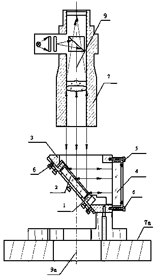
[0029] A method of using a center deviation measuring instrument to adjust the reflector group, such as image 3 , Figure 6 As shown, the mirror group includes a mirror position adjustment block 1, a mirror 2, a mirror seat 3, a flat crystal 4, a flat crystal fixing seat 5, and an inner hexagon screw 6, and the center deviation measuring instrument 7 also includes a gas The floating turntable 7a is characterized in that the installation and adjustment includes the following steps:

[0030] step one: Mirror group installation

[0031] The reflector 2 is bonded in the reflector position adjustment block 1 by glue; the reflector position adjustment block 1 is installed on the reflector seat 3, and the mirror position adjustment block 1 and the reflector seat 3 are adjusted by the hexagon socket screws. The flat crystal 4 is installed on the flat crystal fixed seat 5, and then the flat crystal fixed seat 5 is installed on the reflector seat 3; the reflector seat 3 is fixed on...

Embodiment 2

[0039] A method of using a center deviation measuring instrument to adjust the reflector group, such as Figure 4 , Figure 5 , Figure 7 As shown, the mirror group includes two mirror position adjustment blocks 1, two mirrors 2, mirror holders 3, two flat crystals 4, and hexagon socket screws 6 arranged symmetrically, and the center deviation measuring instrument 7 also includes The air-floating rotary table 7a is characterized in that the installation and adjustment includes the following steps:

[0040] step one: Mirror group installation

[0041] Glue the left and right reflectors 2 to the corresponding left and right reflector position adjustment blocks 1 respectively; install the left and right reflector position adjustment blocks 1 on the corresponding positions of the reflector base 3, Hexagonal screws respectively adjust the position between the left and right mirror position adjustment block 1 and the mirror base 3; install the flat crystal 4 on the mirror base ...


PUM


Abstract

The invention discloses a method for adjusting reflectors through a decentration measuring instrument. An adjusting mechanism comprises reflector position adjusting blocks (1), the reflectors (2), reflector bases (3), optical flats (4), optical flat fixing seats (5), inner hexagon screws (6), the decentration measuring instrument (7) and an air flotation turntable (7a). The method comprises the main steps that the reflectors (2) are fixed in the reflector position adjusting blocks (1) in an adhesive dispensing mode; the relative position of the reflector position adjusting blocks (1) and the reflector bases (3) is adjusted and fixed through the inner hexagon screws (6); the optical flats (4) are arranged on the reflector bases (3); the reflector bases (3) are fixed on the decentration measuring instrument (7). The method mainly achieves the aim that in the process of adjusting high-precision folding type optical lenses, mounting of the reflectors and the actual optical centre positions of the lenses can be monitored and adjusted in real time, the adjusting efficiency of the high-precision folding type optical lenses is improved, adjusting cost is lowered, and the imaging quality of the lenses is guaranteed.

Description

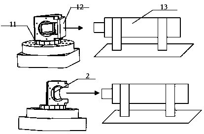
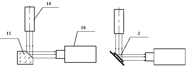
Technical field [0001] The present invention involves a method of using the center -to -measurement reflex mirror of the center.Especially for the reflex mirror of high -precision folding optical lenses and the position of the center of each lens group. Background technique [0002] [0003] At present, the installation of high -precision folding optical lens mainly uses self -standard direct, laser and other equipment.exist figure 1 In the middle, the self -allowed straight 13 to checked the 0 ° school through the flat film 12, and then the rotating precision rotation platform 11 to 45 ° and adjusting the position of the reflex mirror 2, so that the reflex mirror 2 and the self -standard straight 13 were 90 °.The angle of reflector 2 is guaranteed by the angle accuracy of the precision rotation platform 11.exist figure 2 Among the laser transmitters 14 reflected the parallel light emitted into the receiver 16 through the standard prism 15, the receiver 16 and the laser transmitt...

Claims


Application Information

Patent Timeline
IPC IPC(8): G02B7/198
CPCG02B7/198
Inventor 陈骥木锐杨伟声黄攀李洪兵罗永芳贾钰超
Owner YUNNAN KIRO CH PHOTONICS
Learn More