
Flexible bionic tail fin with embedded drive joints and multiple motion modes

A multi-motion mode, intra-joint technology, applied to non-rotating propulsion elements and other directions, can solve the problems of high maintenance and replacement costs, complex structure, single motion mode, etc., and achieve the effect of high motion execution efficiency and easy installation.

Active Publication Date: 2015-01-28
严格集团股份有限公司
View PDF8 Cites 13 Cited by
  • Summary
  • Abstract
  • Description
  • Claims
  • Application Information

AI Technical Summary

Problems solved by technology

[0007] The present invention aims to solve the problems existing in the existing underwater imitation caudal fin propulsion device, such as complex structure, high cost of maintenance and replacement, single motion mode, large gap between bionic effect and real fish swimming in nature, and further provides a driving joint Built-in flexible multi-sport mode bionic caudal fin

Method used


Image

  • Flexible bionic tail fin with embedded drive joints and multiple motion modes
  • Flexible bionic tail fin with embedded drive joints and multiple motion modes
  • Flexible bionic tail fin with embedded drive joints and multiple motion modes

Examples


specific Embodiment approach 1

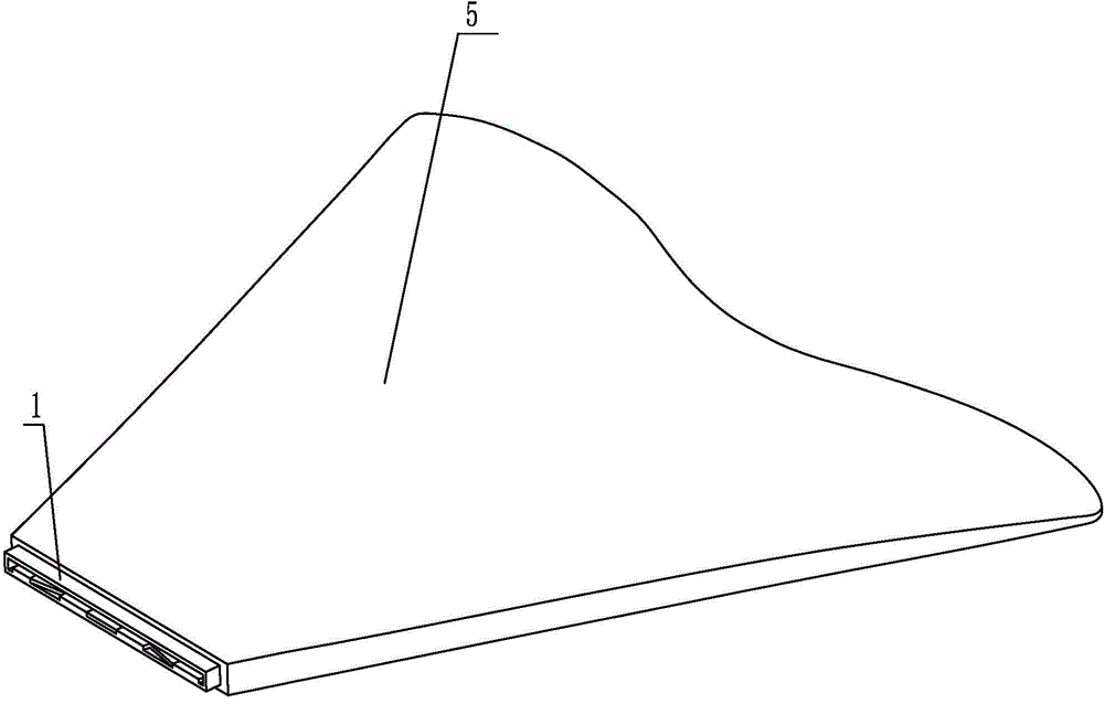
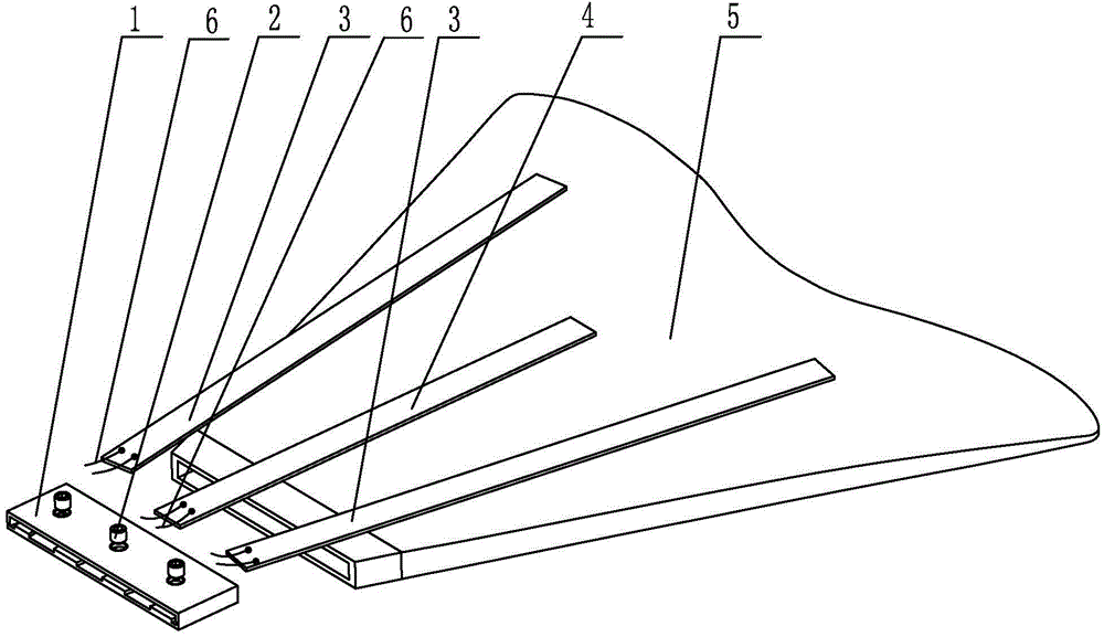
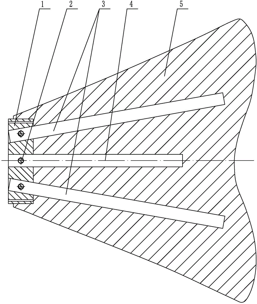
[0015] Specific implementation mode one: combine Figure 1-Figure 5 Explain that the flexible multi-motion mode bionic caudal fin with built-in driving joints in this embodiment includes a bionic flexible skin 5, an elastic clamping frame 1, a first piezoelectric fiber composite driving joint 4 and N second piezoelectric fiber composite Material-driven joint 3; where N is an even number, and N≥2;

[0016] The elastic clamping frame 1, the first piezoelectric fiber composite material driving joint 4 and N second piezoelectric fiber composite material driving joints 3 are embedded in the flexible skin 5, the first piezoelectric fiber composite material driving joint 4 and the Nth Two piezoelectric fiber composite driving joints 3 are detachably connected to the elastic clamping frame 1 respectively. The first piezoelectric fiber composite driving joint 4 is horizontally arranged in the middle of the bionic flexible skin 5 along the axial direction. N second piezoelectric The fi...

specific Embodiment approach 2

[0018] Specific implementation mode two: combination Figure 1-Figure 3 Note that the bionic flexible skin 5 in this embodiment is made of silica gel. With such setting, the chemical properties are stable, and the mechanical strength is relatively high, which meets the design requirements and actual needs.

specific Embodiment approach 3

[0019] Specific implementation mode three: combination Figure 1-Figure 3Note that the elastic clamping frame 1 in this embodiment is made of silica gel or polytetrafluoroethylene. With such a setting, it is convenient to use and easy to obtain materials. Others are the same as in the first or second embodiment.


PUM


Abstract

The invention discloses a flexible bionic tail fin with embedded drive joints and multiple motion modes, relates to a tail fin and aims to solve the problems that according to an existing underwater bionic tail fin pushing device, structure is complex, maintenance and replacement costs are high, the motion mode is single, and the bionic effect is far from the natural actual fish swimming effect. The flexible bionic tail fin comprises a flexible bionic skin, an elastic clamping frame, a first piezoelectric fiber composite drive joint and N second piezoelectric fiber composite drive joints. The elastic clamping frame, the first piezoelectric fiber composite drive joint and the N second piezoelectric fiber composite drive joints are embedded in the flexible bionic skin, the first piezoelectric fiber composite drive joint and the N second piezoelectric fiber composite drive joints are detachably connected to the elastic clamping frame respectively, and the first piezoelectric fiber composite drive joint is arranged in the middle of the flexible bionic skin axially and horizontally. The flexible bionic tail fin belongs to the field of fish-simulation underwater pushing devices.

Description

technical field [0001] The invention relates to a caudal fin, in particular to a bionic caudal fin with flexible multi-movement modes, which belongs to the field of fish-like underwater propulsion devices. Background technique [0002] Most of the traditional underwater thrusters use the propeller as the drive unit. Practice has proved that there are many inevitable problems in this method, such as heavy weight, large volume, high energy consumption, low efficiency, poor reliability, poor maneuverability, and Accompanied by large noise and wake vortex, it has a certain negative impact on the survival of marine organisms and the environment. These shortcomings limit its application in the field of underwater vehicles to a certain extent. In the past 10 years, with the gradual acceleration of the pace of human use and development of the ocean, bionic underwater vehicles have also been gradually developed. Among this type of vehicles, fish-like robots are the most popular. ...

Claims


Application Information

Patent Timeline
Patent Type & Authority Applications(China)
IPC IPC(8): B63H1/36
Inventor 陈维山董帝渤郝亚强刘军考侯珍秀
Owner 严格集团股份有限公司
Learn More