A method of using a soymilk machine to make rich and nutritious soymilk
A soymilk maker and soymilk technology, which is applied in applications, dairy products, milk substitutes, etc., can solve the problems of long production cycle of soymilk, enhancement of soymilk fragrance, and loss of fragrance, etc., and achieve the effect of better soymilk flavor, mellow taste and strong fragrance
- Summary
- Abstract
- Description
- Claims
- Application Information
AI Technical Summary
Problems solved by technology
Method used
Image
Examples
Embodiment approach 1
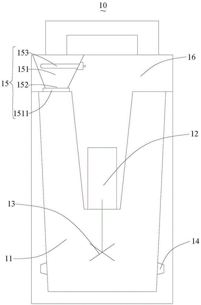
[0035] see figure 1 The schematic diagram of the soymilk machine used in the first preferred embodiment of the method for making strong-flavored nutritious soymilk, the soymilk machine 10 includes a pulping container 11, a motor 12, a crushing tool 13, a heating element 14, a baking device 15 and a control unit (not shown), the motor 12 drives the crushing tool 13 to rotate, the crushing tool 13 is located in the pulping container 11, the heating element 14 heats the pulping container 11, the motor 12, the heating element 14 and the baking device 15 are connected with the control The unit is electrically connected.
[0036] In this embodiment, the pulping container 11 is a cup body of an ordinary existing soybean milk machine.
[0037] In this embodiment, the soymilk machine 10 includes a machine head 16 which is buckled on the cup body, and the baking device 15 and the motor 12 are arranged on the machine head 16 . The baking device 15 includes a baking bin 151 with a feedi...
Embodiment approach 2
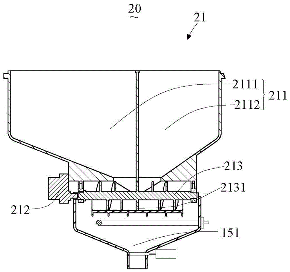
[0052] see figure 2 A schematic diagram of the soymilk maker used in the first preferred embodiment of the method for making strong-flavored nutritious soymilk. The difference between the soymilk maker 20 and the soymilk maker 10 is that the soymilk maker 20 also includes the storage assembly 21. The material storage assembly 21 includes a storage bin 211, a motor 212, and a feeding screw 213. The storage bin 211 includes a feeding opening. The feeding screw 213 is fixedly installed under the storage bin 211 and adjacent to the feeding opening. , the baking bin 151 is located below the feeding screw 213 , the motor 212 is electrically connected to the control unit, and the motor 212 drives the feeding screw 213 to rotate to drive materials from the storage bin 211 to the baking bin 151 .
[0053] In this embodiment, the storage bin 211 includes a first storage bin 2111 and a second storage bin 2112, the first storage bin 2111 includes a first discharge opening, and the second...
PUM
 Abstract
Description
Claims
Application Information
 - R&D Engineer
- R&D Manager
- IP Professional
- Industry Leading Data Capabilities
- Powerful AI technology
- Patent DNA Extraction
Browse by: Latest US Patents, China's latest patents, Technical Efficacy Thesaurus, Application Domain, Technology Topic, Popular Technical Reports.
© 2024 PatSnap. All rights reserved.Legal|Privacy policy|Modern Slavery Act Transparency Statement|Sitemap|About US| Contact US: help@patsnap.com


