Wireless power harvesting along multiple paths in reverberent cavity

A cavity, electric technology, applied in the direction of antennas, antennas, circuits, etc. suitable for movable objects, which can solve the problems of inconsistency and unreliable collection.

Active Publication Date: 2015-01-21
THE BOEING CO
View PDF8 Cites 1 Cited by
  • Summary
  • Abstract
  • Description
  • Claims
  • Application Information

AI Technical Summary

Problems solved by technology

However, collection from ambient sources is unreliable and inconsistent, and, for closed structures such as fuel tanks, may not be feasible

Method used


Image

  • Wireless power harvesting along multiple paths in reverberent cavity
  • Wireless power harvesting along multiple paths in reverberent cavity
  • Wireless power harvesting along multiple paths in reverberent cavity

Examples


Embodiment Construction

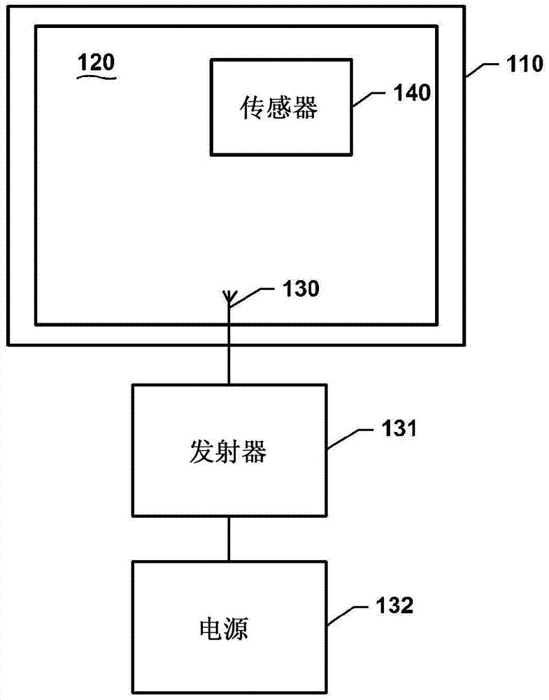
[0034] refer to figure 1 , shows a structure 110 having a cavity 120, and a source for exciting the cavity with electromagnetic energy. The excitation source includes a radiation unit 130 inside the cavity 120 , an emitter 131 and a power source 132 outside the cavity 120 . Although shown outside the cavity, the emitter 131 may alternatively be located inside the cavity.

[0035] When excited with electromagnetic energy, the cavity 120 reflects the energy and generates a standing wave electric field. The walls 122 of the cavity 120 may be made of a material that reflects electromagnetic energy (eg, metal), or the walls 122 may be coated or covered with a material that reflects electromagnetic energy (eg, paint or foil). The wavelength of the electromagnetic energy is small compared to the size of the cavity 120 . The length of the smallest dimension of cavity 120 may be several wavelengths long. For example, the cavity 120 of a fuel tank of a commercial aircraft may be exc...


PUM


Abstract

An apparatus comprises a structure including a cavity that, when excited with electromagnetic energy, produces an electric field having randomized distribution of field amplitude and polarity. The apparatus further comprises a sensor within the cavity. The sensor has a plurality of antennas for wirelessly harvesting operating power along different paths within the cavity.

Description

Background technique [0001] In commercial aircraft, sensors may be located in fuel tanks to measure temperature, moisture content, fuel level, oxygen level, and other physical quantities. Because US federal government regulations prohibit power storage devices, such as batteries and supercapacitors, from being located inside the fuel tank, the sensor receives power from a power source outside the fuel tank. [0002] Power can be provided to the sensor via wires running into the fuel tank. This wire can also be used for data communication. However, wires add weight to the aircraft. The added weight increases the operating costs of the aircraft. Wiring also increases maintenance costs by requiring inspection. [0003] In the alternative, the sensor may harvest energy from sources in the surrounding environment (eg, vibration, thermal energy, and solar energy). However, collection from ambient sources is unreliable and inconsistent, and, for closed structures such as fuel ta...

Claims


Application Information

Patent Timeline
Patent Type & Authority Applications(China)
IPC IPC(8): H02J7/02H02J17/00
CPCH02J17/00H01Q1/00H01Q1/2225H01Q1/225H01Q1/28H02J50/20H02J50/005H02J50/001H02J50/402H02J50/90H02J50/40H02J50/27
Inventor 杰森·P·博默尔阿伦·阿亚加里
Owner THE BOEING CO
Why Eureka
Try Eureka