A manual closing mechanism and high-voltage switchgear equipped with the closing mechanism

A manual closing, high-voltage switch technology, applied in electrical switches, contact operating mechanisms, high-voltage air circuit breakers, etc., can solve the problems of reduced product reliability, no speed, normal line power failure, etc., to achieve high reliability. , Simple structure, simple processing effect

Active Publication Date: 2017-01-11
SUZHOU CLOU MGE ELECTRIC
View PDF5 Cites 0 Cited by
  • Summary
  • Abstract
  • Description
  • Claims
  • Application Information

AI Technical Summary

Problems solved by technology

[0003] Now the monostable permanent magnet mechanism can basically realize manual opening with speed, but manual closing is difficult to achieve manual closing with speed because it needs to overcome the reaction force of the contact spring and opening spring
[0004] There are also many designs of manual closing devices in the existing products equipped with permanent magnet operating mechanisms, which are basically divided into two situations: one is the complex structure, and this design has deviated from the simple and reliable structure of permanent magnet operating mechanisms. High characteristics reduce the reliability of the product; the other is closing without speed. This design requires a power outage at the upper level of the line. Manual closing without power will cause power outages on normal lines. Can not meet the actual use requirements of users

Method used


Image

  • A manual closing mechanism and high-voltage switchgear equipped with the closing mechanism
  • A manual closing mechanism and high-voltage switchgear equipped with the closing mechanism
  • A manual closing mechanism and high-voltage switchgear equipped with the closing mechanism

Examples


Embodiment Construction

[0029] The present invention will now be further described in detail in conjunction with the accompanying drawings and embodiments. These drawings are all simplified schematic diagrams, only illustrating the basic structure of the present invention in a schematic manner, so it only shows the composition related to the present invention.

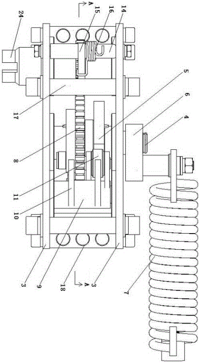
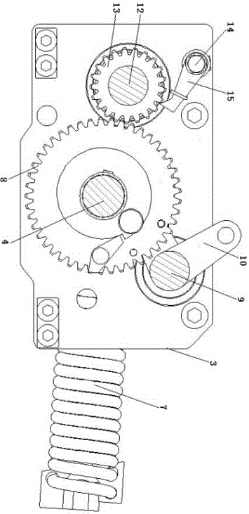
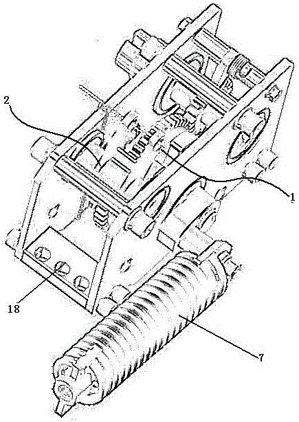
[0030] As shown in Figure-5, a manual closing mechanism 19 includes: a spring energy storage mechanism arranged on the support side plate 3 and a closing lever mechanism 2, the spring energy storage mechanism is provided with an energy storage shaft 4, and the energy storage The shaft 4 is fixed in series with a driving mechanism, a spring energy storage arm 6 and a cam 5. The closing arm mechanism 2 is provided with a rotating shaft 9, and the rotating shaft 9 is provided with a closing output arm 10 and a roller 11. Set close to the side circumference of the cam 5, the cam 5 can drive the closing output toggle arm 10 to rotate through the ro...


PUM


Abstract

The invention relates to a manual closing mechanism and high-voltage switch equipment with the manual closing mechanism. The manual closing mechanism comprises a spring energy storage mechanism and a closing connecting lever mechanism arranged on supporting side plates and is characterized in that the spring energy storage mechanism is provided with an energy storage shaft, the energy storage shaft is fixedly sleeved with a driving mechanism, a spring energy storage connecting lever and a cam in series, the closing connecting lever mechanism is provided with a rotary shaft, a closing output connecting lever and a rolling wheel are arranged on the rotary shaft, the rolling wheel is arranged by being closely attached to the side circumference of the cam, the cam can drive the closing output connecting lever to rotate through the rolling wheel, one end of the spring energy storage connecting lever is connected with the energy storage shaft, and the other end of the spring energy storage connecting lever is connected with a manual closing spring. The manual closing mechanism and the high-voltage switch equipment have the advantages that the structure is simple, reliability is high, closing with speed can be achieved, and the closing success rate is 100 percent; meanwhile, the motion law of a permanent magnet operating mechanism arranged in the high-voltage switch equipment is not influenced by the manual closing mechanism, and the permanent magnet operating mechanism and the manual closing mechanism are matched perfectly.

Description

technical field [0001] The invention belongs to the technical field of high-voltage switchgear, and relates to a high-voltage switchgear equipped with a permanent magnet operating mechanism, in particular to a manual closing mechanism and the high-voltage switchgear equipped with the closing mechanism. Background technique [0002] The application of high-voltage switches equipped with permanent magnet operating mechanism in my country's distribution network is expanding day by day, mainly due to the simple structure and high reliability of the permanent magnet operating mechanism, which can better realize precise control and fast opening. . However, products equipped with permanent magnet operating mechanisms must have a power supply for their opening and closing operations. Many distribution network products are installed on outdoor utility poles, and their power supply depends on the power transformer on the line, or the power transformer supplies power to the control box....

Claims


Application Information

Patent Timeline
Patent Type & Authority Patents(China)
IPC IPC(8): H01H3/22H01H31/02
CPCH01H3/3005H01H31/026
Inventor 杜凯钟锦汉李佳
Owner SUZHOU CLOU MGE ELECTRIC
Why Eureka
Try Eureka