Hydraulic damping cylinder and pneumatic driving device and wiper using the damping cylinder

A hydraulic damping and pneumatic drive technology, applied in the fields of pneumatic drive devices, wipers, and hydraulic damping cylinders, can solve problems such as failure to meet the requirements of EMUs, difficult control of piston feed speed, and unstable swing of wipers, etc. Motion stability and stop accuracy, simple action mode control, and the effect of reducing processing costs

Active Publication Date: 2017-01-25
XINXIANG AVIATION IND GROUP
View PDF8 Cites 0 Cited by
  • Summary
  • Abstract
  • Description
  • Claims
  • Application Information

AI Technical Summary

Problems solved by technology

[0002] Chinese patent document CN203681493U discloses a purely air-controlled pneumatic wiper motor for rail locomotives. The driving device of the wiper is a rotary swing cylinder, which has the characteristics of large output torque and locking torque, and a wide speed regulation range. But at the same time, because the power source of the rotary swing cylinder is compressible gas, it is difficult to control the feed speed of the piston, and it is easy to generate vibration, resulting in unstable swing of the wiper.
Especially when the rotary swing cylinder works quickly, when the wiper changes direction and swings, the impact of the wiper is often caused by the inertia of the rotary swing cylinder, which will damage the wiper.
Like this, the driving device of existing wiper just can't satisfy the use requirement of the EMU above 300km / h per hour.

Method used


Image

  • Hydraulic damping cylinder and pneumatic driving device and wiper using the damping cylinder
  • Hydraulic damping cylinder and pneumatic driving device and wiper using the damping cylinder

Examples


Embodiment Construction

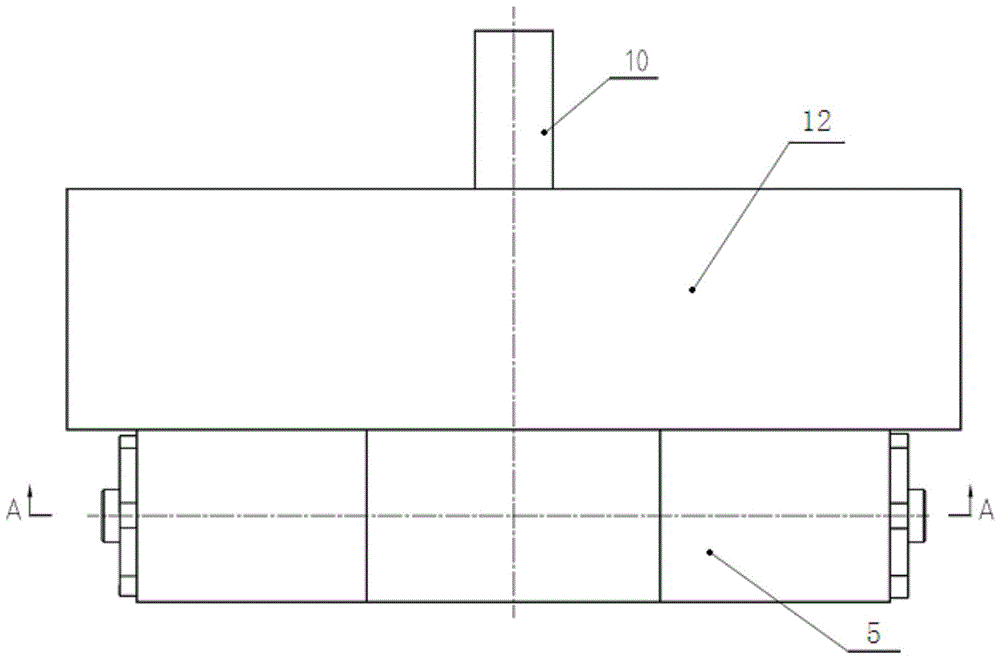
[0019] Such as figure 2 The hydraulic damping cylinder shown includes a damping cylinder and a damping piston 6 that moves left and right in the piston cavity of the damping cylinder. The inner damping gear 11 is meshed for transmission, and the inner hole of the damping gear is the mounting hole of the corresponding power output shaft.

[0020] The damping cylinder body includes the damping cylinder body and the cylinder heads 3 installed on the left and right ends of the damping cylinder body. In order to facilitate disassembly and assembly, the two cylinder heads are screw-mounted on the damping cylinder body 5, and there are oil injection holes running through the two cylinder heads. hole, screw-fit plug 1 on the oil hole. The damping piston 6 divides the damping cylinder into two oil chambers, that is, the left oil chamber and the right oil chamber respectively located at the left and right ends of the damping piston. A cylinder head seal ring 4 is installed between th...


PUM


Abstract

The invention relates to a hydraulic damping cylinder and a pneumatic driving device comprising the damping cylinder as well as a wiper. The hydraulic damping cylinder comprises a damping cylinder body, a damping gear, and a damping piston which is capable of moving left and right in the piston chamber of the damping cylinder body, wherein the damping piston is engaged with the damping gear for transmission by use of a rack arranged on the damping piston and extending in the left-and-right direction; an oil return channel is further formed in the damping piston and used for communicating left and right oil chambers located at the two ends of the damping piston; the oil return channel is provided with a damping hole structure; the inner hole of the damping gear is a mounting hole for a corresponding power output shaft. The pneumatic driving device is capable of improving the motion stability and the stop position accuracy of the output shaft of a rotary oscillating cylinder when the rotary oscillating cylinder works fast by virtue of the incompressibility of the hydraulic oil in the hydraulic damping cylinder, and further improving the motion stability and the stop position accuracy of a wiper assembly and the motion reliability of the wiper.

Description

technical field [0001] The invention relates to a hydraulic damping cylinder, a pneumatic driving device and a wiper using the damping cylinder. Background technique [0002] Chinese patent document CN203681493U discloses a purely air-controlled pneumatic wiper motor for rail locomotives. The driving device of the wiper is a rotary swing cylinder. The rotary swing cylinder has the characteristics of large output torque and locking torque, and a wide speed regulation range. But at the same time, because the power source of the rotary oscillating cylinder is compressible gas, it is difficult to control the feed speed of the piston, which is prone to vibration and causes the wiper to swing unsteadily. Especially in the working condition of the rotary oscillating cylinder working quickly, when the wiper is reversing and swinging, the impact of the wiper is often caused by the inertia of the rotary oscillating cylinder, which damages the wiper. Like this, the driving device of e...

Claims


Application Information

Patent Timeline
Patent Type & Authority Patents(China)
IPC IPC(8): F15B15/22
CPCB60S1/10
Inventor 王献岭王玉涛刘建辉王硕贾方迪屈利丽
Owner XINXIANG AVIATION IND GROUP
Why Eureka
Try Eureka