
A pipe wrench capable of quickly adjusting the amount of opening

A technology of opening volume and pipe wrench, applied in the direction of wrench, wrench, manufacturing tool, etc., can solve the problems of time-consuming and laborious, low work efficiency, troublesome operation, etc., and achieve the effect of easy manufacturing, convenient operation and simple structure

Active Publication Date: 2016-05-11
WEIHAISHIWEILI TOP GRADE TOOL CO
View PDF5 Cites 0 Cited by
  • Summary
  • Abstract
  • Description
  • Claims
  • Application Information

AI Technical Summary

Problems solved by technology

[0003] During use, both hands are required to continuously rotate the adjusting nut to repeatedly adjust the opening of the jaws. Therefore, the adjustment speed is slow, time-consuming and labor-intensive.
When clamping pipe workpieces or round pipes, when the jaws of the pipe wrench are under force, the nuts are easy to loosen due to the gap between the nut and the thread, and the clamping jaws will slip, which is easy to damage the surface of the workpiece
In addition, the strength requirements of the fixed jaws, movable jaws and pliers handle body are high, and the fixed jaws and pliers handle body are integrated, so the pipe wrench is bulky and heavy
It is inconvenient to use, cumbersome to operate, time-consuming and labor-intensive, and has low work efficiency

Method used


Image

  • A pipe wrench capable of quickly adjusting the amount of opening
  • A pipe wrench capable of quickly adjusting the amount of opening
  • A pipe wrench capable of quickly adjusting the amount of opening

Examples


Embodiment Construction

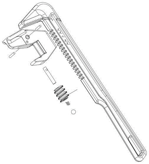
[0015] As shown in the figure, a pipe wrench that can quickly adjust the amount of opening includes a fixed jaw, a movable jaw, a wrench body 1 and a wrench handle 8, the fixed jaw is on the inner side of the front end of the wrench handle 8, and the movable jaw is on the One side of the front end of the wrench body 1 is respectively provided with saw-shaped teeth on the fixed jaw and the movable jaw. There are helical teeth, the handle 8 of the wrench body is provided with a scale, and there is a through hole on one side of the wrench body 1, and the direction of the through hole is perpendicular to the movable jaw. The handle 8 of the wrench body enters the through hole of the wrench body 1, and the wrench body 1 The body handle 8 is movable, and a groove is provided on the pull body 1, the bottom of the groove communicates with the through hole in the axial direction, and a worm 4 is installed in the groove, and the worm 4 meshes with the helical teeth on the inside of the p...


PUM


Abstract

The invention relates to hardware manual tools. A pipe wrench with openness capable of being quickly adjusted comprises a fixed jaw, a movable jaw, a wrench body and a wrench body handle. Sawteeth are arranged on the fixed jaw and the movable jaw respectively, the inner side of the front portion of the wrench body handle is provided with inclined teeth, the wrench body handle is provided with scales, one side of the wrench body is provided with a through hole, the direction of the through hole is perpendicular to the movable jaw, the wrench body handle enters the through hole of wrench body, the wrench body can move on the wrench body handle, a groove is formed in the wrench body, the bottom of the groove is axially communicated with the through hole, a worm is installed in the groove, the worm is meshed with the inclined teeth of the inner side of the wrench body handle, a center hole of the worm is sequentially provided with a backing pin, a spring and a ball from top to bottom, the upper end of the backing pin is provided with a radial through hole, the upper portion of the backing pin is arranged in the groove in the wrench body, the backing pin is hinged to the wrench body through a pin, the side, in contact with the groove wall of the wrench body, of the ball is provided with an arc groove, and a rivet is arranged on the position, on the left lower portion of the pin, of the wrench body. The pipe wrench is simple in structure, easy to manufacture, low in cost, low in weight, easy to operate and convenient to use, saves time and labor and is high in work efficiency, and the openness of the jaws can be quickly adjusted.

Description

technical field [0001] The invention relates to the technical field of hardware hand tools, in particular to a pipe wrench capable of quickly adjusting the amount of opening. Background technique [0002] Most of the pipe wrench currently on the market are composed of fixed jaws, movable jaws, pliers handle body, adjusting nut, etc. The fixed jaws and pliers handle body are integrated, the front end of the pliers handle body is the fixed jaw, and the The inner side is a V-shaped tooth surface, and the front end of the movable jaw is a V-shaped tooth surface. The movable jaw is moved by adjusting the nut to change the size of the opening of the jaw to work. It is widely used in clamping and twisting circular pipe workpieces. When in use, the adjusting nut is rotated, and the nut and the thread cooperate to rotate to adjust the movement of the movable jaw, so that the opening of the movable jaw relative to the fixed jaw changes, and the circular pipe workpiece is clamped. ...

Claims


Application Information

Patent Timeline
Patent Type & Authority Patents(China)
IPC IPC(8): B25B13/50
CPCB25B13/5058
Inventor 宋协会王丽华王宗明
Owner WEIHAISHIWEILI TOP GRADE TOOL CO
Learn More