Eureka AIR delivers breakthrough ideas for toughest innovation challenges, trusted by R&D personnel around the world.

Touch stylus and operating method thereof

An operation method and stylus technology, which are applied to electromechanical devices, instruments, electrical digital data processing, etc., can solve the problems of high manufacturing cost, insufficient power supply, limited type of digital board, etc., so as to avoid insufficient power supply and low manufacturing cost. Effect

Inactive Publication Date: 2015-01-14
RAYDIUM SEMICON
View PDF4 Cites 4 Cited by
  • Summary
  • Abstract
  • Description
  • Claims
  • Application Information

AI Technical Summary

Problems solved by technology

[0004] (1) It is easy to have insufficient power supply
[0005] (2) The types of digital boards that can be used are limited
[0006] (3) The user needs to replace the battery
[0007] (4) Higher manufacturing cost

Method used


Image

  • Touch stylus and operating method thereof
  • Touch stylus and operating method thereof
  • Touch stylus and operating method thereof

Examples


Embodiment Construction

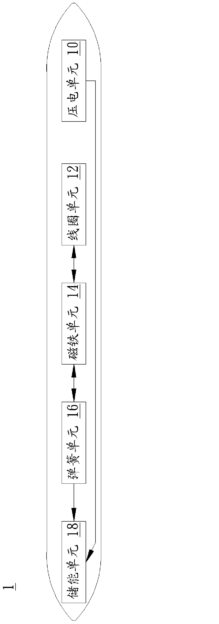
[0040] A specific embodiment according to the present invention is a touch pen. In this embodiment, the touch pen is used to perform a touch action on the touch panel of the electronic device, but not limited to this. First, please refer to figure 1 , figure 1 A functional block diagram of the stylus in this embodiment.

[0041] like figure 1 As shown, the stylus 1 includes a piezoelectric unit 10 , a coil unit 12 , a magnet unit 14 , a spring unit 16 and an energy storage unit 18 . The piezoelectric unit 10 is coupled to the energy storage unit 18 ; the coil unit 12 is coupled to the magnet unit 14 ; the magnet unit 14 is coupled to the spring unit 16 ; the spring unit 16 is coupled to the energy storage unit 18 .

[0042] As for the coil unit 12 and the magnet unit 14, the up and down or left and right movements of the stylus 1 can be accepted, so that the relative movement between the coil unit 12 and the magnet unit 14 changes the distance between the two, resulting in...


PUM


Abstract

A touch stylus and operating method thereof are disclosed. The touch stylus includes a piezoelectric unit, a magnet unit, and a coil unit. The piezoelectric unit is formed by a piezoelectric material. The magnet unit is coupled to the piezoelectric unit. The coil unit is evenly wound on the outer of the magnet unit. When a tip of the touch stylus is forced and generates a vibration, the piezoelectric material of the piezoelectric unit is deformed by force to generate a piezoelectric current. When the touch stylus is shaken, the coil unit and the magnet unit will generate relative movement to change the distance between them and the magnetic flux will be changed, the coil unit will generate an induced current.

Description

technical field [0001] The present invention relates to a touch input device, and more particularly, to a touch stylus and an operating method thereof. Background technique [0002] Generally speaking, a conventional stylus can be in the form of a piezoelectric self-powered card, which can include a card body, a piezoelectric sheet, and an electronic device. The card body has flexibility and elasticity; the piezoelectric sheet is made of piezoelectric material and is arranged in the card body. When the card body is deformed by force, the piezoelectric sheet will generate electrical energy, and the electronic device will receive the electrical energy from the piezoelectric sheet as a driving power source for the stylus. [0003] However, the above-mentioned conventional piezoelectric self-powered card-type stylus also has the following disadvantages: [0004] (1) It is easy to have insufficient power supply [0005] (2) The types of digital boards that can be used are limi...

Claims


Application Information

Patent Timeline
Patent Type & Authority Applications(China)
IPC IPC(8): H02N2/18H02K35/02G06F3/0354
CPCG06F3/016G06F3/03545G06F1/3259H02K35/02H02N2/18Y02D10/00
Inventor 吕雅玲林德昌曾国宗林佳秀陈义明郑为元
Owner RAYDIUM SEMICON
Why Eureka
Eureka Blog
Learn More