
Method and device for position adjustment of objective lens in optical pickup head

A technology for adjusting devices and pickup heads, which is applied in the optical field, can solve problems such as reduced production efficiency, low accuracy and stability, and time-consuming, and achieve the effect of improving adjustment efficiency and ensuring accuracy and stability

Inactive Publication Date: 2018-02-02
DONGGUAN HUAQIANG INFORMATION TECH CO LTD
View PDF2 Cites 0 Cited by
  • Summary
  • Abstract
  • Description
  • Claims
  • Application Information

AI Technical Summary

Problems solved by technology

Therefore, the adjustment of the radial position and the tangential position of the objective lens affect each other, resulting in that the objective lens cannot be quickly adjusted to the desired optimal position during the adjustment process, and the adjustment of the radial position and the tangential position needs to be adjusted repeatedly. Takes time and reduces productivity
And this kind of scheme is completed by adjusting the length of the screw stroke of the knob screw, and its accuracy and stability are low

Method used


Image

  • Method and device for position adjustment of objective lens in optical pickup head
  • Method and device for position adjustment of objective lens in optical pickup head

Examples


Embodiment 1

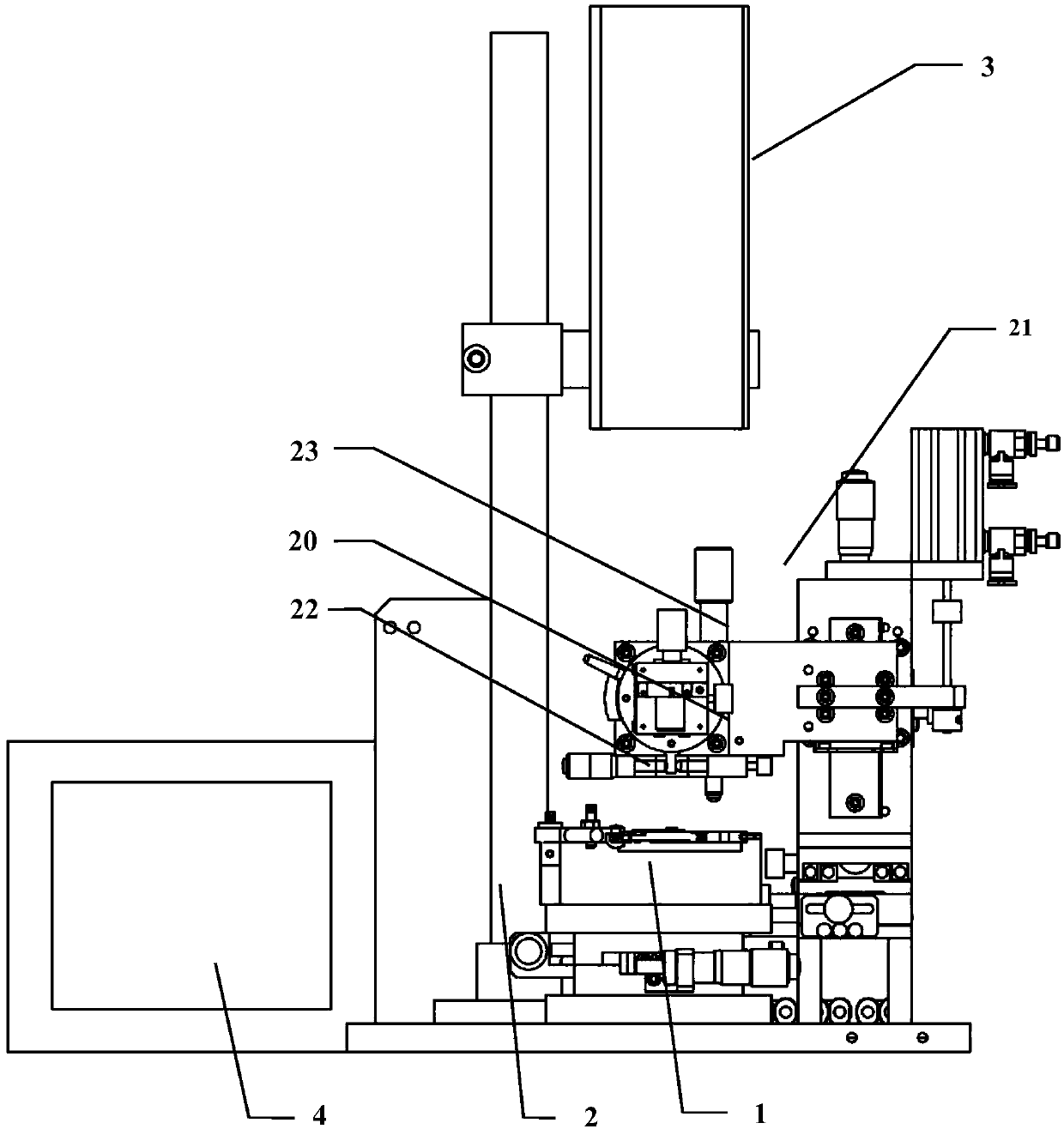
[0034] This embodiment provides a device for adjusting the position of the objective lens in the optical pickup head, the structure of the device, and the connection schematic diagram between the optical pickup head and the optical pickup head are as follows: figure 1 shown in figure 1 Among them, it includes a fixed frame 1 of the optical pickup, and a device 2 connected to the fixed frame 1 to adjust the position of the objective lens in the optical pickup, a collimator device 3 and a display 4 . Wherein the fixed frame 1 is used to fix the optical pickup head, the fixed frame 1 is installed on the above-mentioned device 2 through the slide table base in the horizontal mode of the optical pickup head, and the position of the optical pickup head is adjusted by the slide table base , make the position of the optical pickup objective lens consistent with the position of the adjustment guide frame 20 front, back, left, and right.

[0035] In practical applications, the above-me...

Embodiment 2

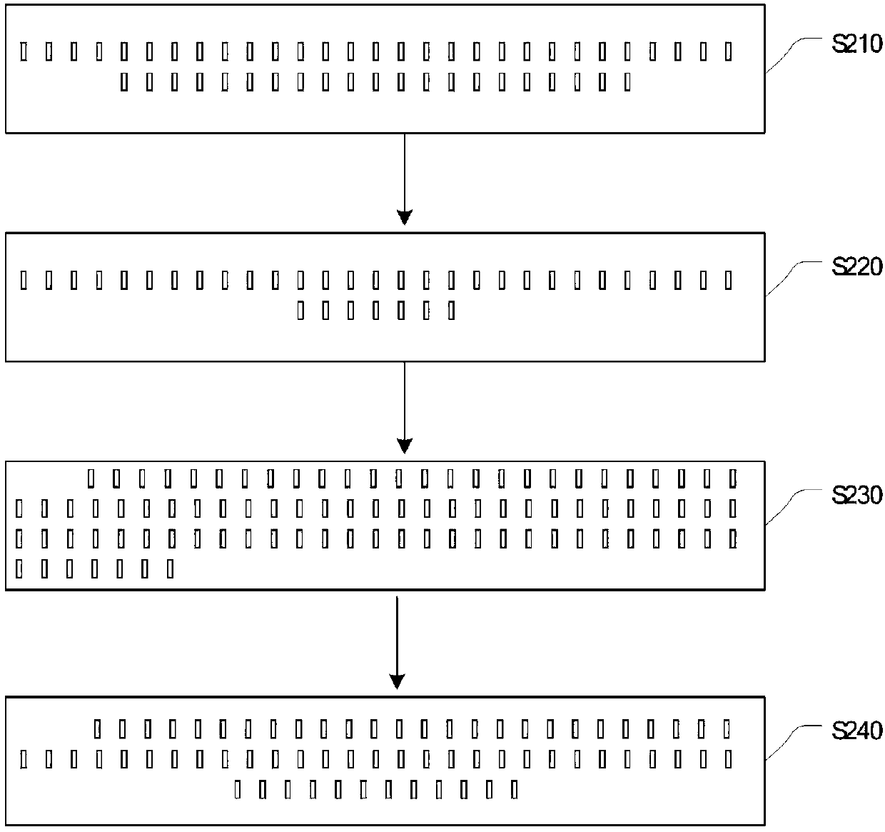
[0048] Based on the above figure 1 Described device, the processing flow of a kind of method that this embodiment provides to the objective lens in the optical pick-up position adjustment is as follows figure 2 As shown, the following processing steps are included:

[0049] Step S210, setting the device for adjusting the position of the objective lens in the optical pickup head including the objective lens guide frame, height adjustment knob, tangential adjustment device and radial adjustment device, the device can be connected with the fixed mount of the optical pickup head, Also included in the optical pickup is a collimator device and a display.

[0050] Step S220 , when the objective lens in the optical pickup head moves toward the optical disc, contact the objective lens guide frame with the objective lens.

[0051] After the focus servo of the actuator in the optical pickup head is connected to a certain working voltage, the objective lens holder of the actuator has t...


PUM


Abstract

The embodiment of the invention provides a method and device for adjusting the position of an objective lens in an optical pick-up head. The device mainly comprises a tangential adjusting device, a radial adjusting device and an objective lens guide frame, wherein the tangential adjusting device is used for adjusting the tangential displacement of the objective lens guide frame in the tangential direction of the objective lens, the radial adjusting device is used for adjusting the radial displacement of the objective lens guide frame in the radial direction of the objective lens, the objective lens guide frame is used for making contact with the objective lens when the objective lens in the optical pick-up head moves towards an optical disc, the radial position of the objective lens can be adjusted through displacement of the objective lens guide frame in the radial direction of the objective lens, and the tangential position of the objective lens can be adjusted through displacement of the objective lens guide frame in the tangential direction of the objective lens. According to the method and device for adjusting the position of the objective lens in the optical pick-up head, the objective lens can be fast adjusted to the needed optimal position so that the position adjustment efficiency of the objective lens can be improved, and compared with the scheme of knob screw adjustment in the prior art, the accuracy and the stability of the position adjustment of the objective lens can be guaranteed.

Description

technical field [0001] The invention relates to the field of optical technology, in particular to a method and a device for adjusting the position of an objective lens in an optical pickup head. Background technique [0002] An optical pickup is a device that uses optical properties to read data recorded on an optical disc. The above-mentioned devices can be CDs, DVDs, and BDs. Existing optical pick-ups mainly include actuators of focus tracking servos, laser diodes, half mirrors, objective lenses, lenses and photodiodes. The optical pickups of the entire optical pick-up are guaranteed by position adjustment and reference spacing adjustment. Axis coincident and perpendicular to the surface of the disc. The function of the objective lens is to focus the laser light emitted from the laser diode into extremely small light spots, and emit the light spots to the pits on the surface of the optical disc. [0003] In order to make the light spot focused by the objective lens hit t...

Claims


Application Information

Patent Timeline
Patent Type & Authority Patents(China)
IPC IPC(8): G11B7/095G11B7/135
CPCG11B7/0925G11B7/0935G11B7/1374
Inventor 王学军吴腾涛宗黎廖志坚
Owner DONGGUAN HUAQIANG INFORMATION TECH CO LTD
Learn More