LED (light emitting diode) lamp assembling azimuth correction device and LED lamp assembling azimuth correction method

A technology of LED lights and azimuths, which is applied in the direction of lighting devices, workpiece clamping devices, components of lighting devices, etc., can solve the problems of no correction device and detection device, poor stability of electrical connection, etc., and achieve the effect of facilitating automatic assembly

Active Publication Date: 2015-01-14
LEEDARSON LIGHTING FIXTURES CO LTD
View PDF7 Cites 8 Cited by
  • Summary
  • Abstract
  • Description
  • Claims
  • Application Information

AI Technical Summary

Problems solved by technology

[0003] Although this method can conveniently complete the assembly of the lamp without screws and glue for connection and fastening, the connection terminal of the power drive device is mechanically fixed by the buckle wire and the groove, and there is no correction device and detection device. Connection stability is poor

Method used


Image

  • LED (light emitting diode) lamp assembling azimuth correction device and LED lamp assembling azimuth correction method
  • LED (light emitting diode) lamp assembling azimuth correction device and LED lamp assembling azimuth correction method
  • LED (light emitting diode) lamp assembling azimuth correction device and LED lamp assembling azimuth correction method

Examples


Embodiment Construction

[0015] The present invention will be further described in detail below in conjunction with the accompanying drawings and specific embodiments.

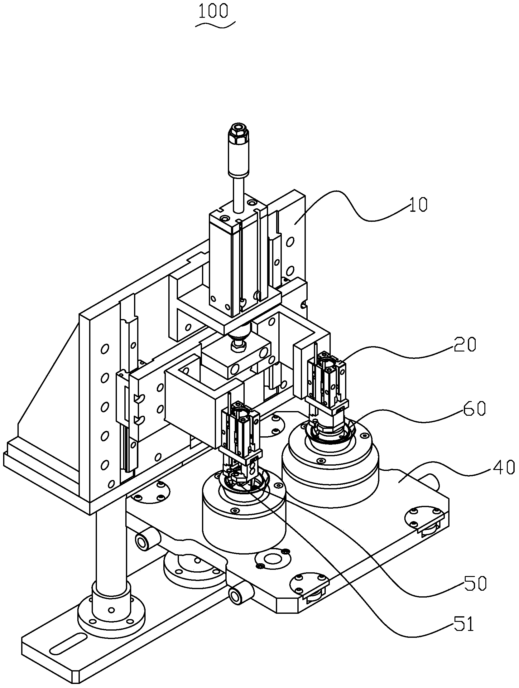
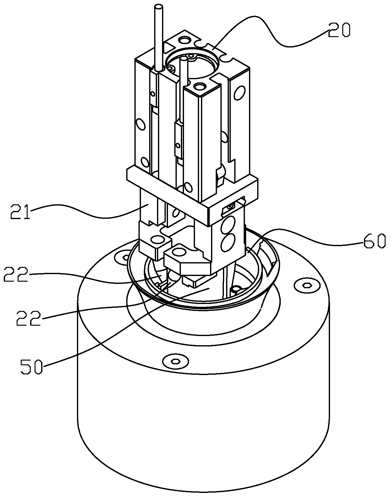
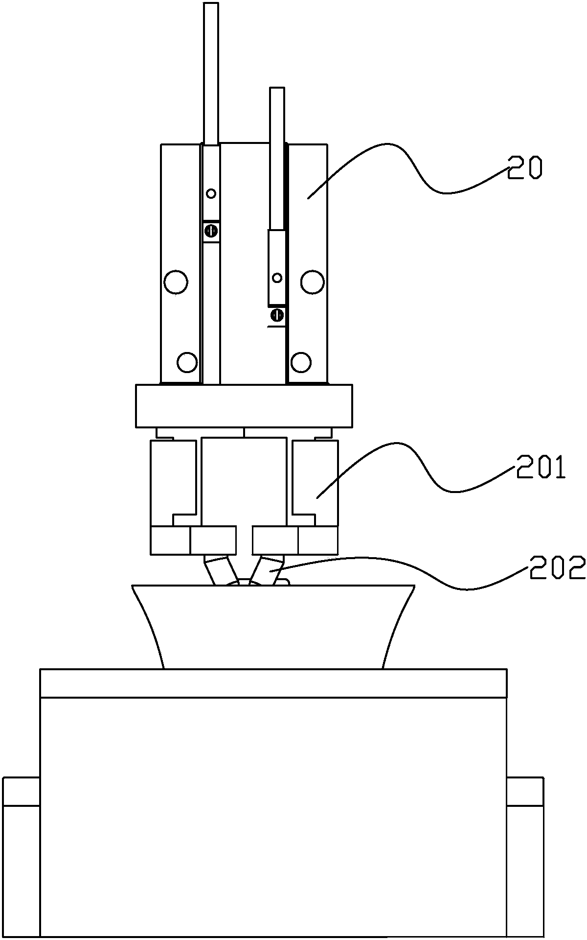
[0016] figure 1 It is a perspective view of an LED lamp assembly orientation correction device 100 according to the first embodiment of the present invention. The LED lamp assembly orientation correction device 100 includes a drive board orientation detection mechanism 10, a drive board orientation correction mechanism 20, and a drive board orientation rotation mechanism (not shown in the figure). ), tooling board 40, driving board 50 and lamp cup 60. The driving plate 50 is assembled in the lamp cup 60 and its position is fixed relative to the lamp cup 60 . When the driving plate 50 is rotated, the lamp cup 60 will also rotate synchronously. One side of the drive board 50 protrudes outwards and is equipped with electronic components 51 (such as Figure 4 shown). The drive board orientation detection mechanism 10 is used to determi...


PUM


Abstract

The invention relates to an LED (light emitting diode) lamp assembling azimuth correction device and an LED lamp assembling azimuth correction method. A LED lamp with the correction function comprises a lamp cup and a drive board, wherein one side of the drive board protrudes outwards to be provided with an electronic element. The LED lamp assembling azimuth correction device is characterized by comprising a drive board azimuth detection mechanism, a drive board azimuth rotating mechanism and a correction mechanism, wherein the drive board azimuth detection mechanism is used for judging the direction of the electronic element on the drive board; the drive board azimuth detection mechanism controls the drive board azimuth rotating mechanism, if the electronic element on the drive board does not generally face a predetermined first direction, the lamp cup is rotated by the rotating mechanism, so that the electronic element on the drive board generally faces the first direction; the correction mechanism comprises a clamping arm and at least two opposite clamping ends which are arranged on the clamping arm, the clamping ends of the clamping arm stretch into the lamp cup at an unfolding state, and the clamping ends are folded to clamp and correct the azimuth of the drive board. The LED lamp assembling azimuth correction device and method have advantage of convenience in automatic assembling.

Description

technical field [0001] The invention relates to an automatic LED lamp assembly device, in particular to an LED lamp assembly orientation correction device and assembly orientation correction method. Background technique [0002] In recent years, with the rapid growth of demand for LED bulb lamps, the production capacity and output of various manufacturers have increased significantly, and the demand for production capacity of existing LED bulb lamps has also continued to increase; while the current production of LED lamps However, both foreign and domestic production models are still dominated by traditional manual operations, and the capacity of traditional production operation models will not be able to meet the huge demand of the market. The structure of LED lamps is mainly composed of light source components, power components, radiators, lampshades, lamp holders, connectors and other components. At present, most LED lamps are assembled manually, relying on crowd tactics...

Claims


Application Information

Patent Timeline
Patent Type & Authority Applications(China)
IPC IPC(8): F21V17/00B25B11/00F21Y101/02
CPCB25B11/00F21V17/00
Inventor 张洋龙威何俊超何良友吴昌县李永川李其灵
Owner LEEDARSON LIGHTING FIXTURES CO LTD
Why Eureka
Try Eureka