


Quick Research
Generate reliable direction feasibility study reports for your R&D in just a few steps.

Technical Q&A
Discover and master advanced knowledge NOW. Basics, ideas, possibilities, all at once.

Find Solutions
As an expert in R&D theories, this can generate solutions to your technical problems instantly.

Evaluate Feasibility
Analyze your overall solution with one click, know your potential R&D risks in advance.

Monitor Landscape
Get weekly tech updates, stay abreast of the latest tech innovations and key insights.
Vane wheel
A page and page board technology, applied in the field of page wheel, can solve the problem of low conversion rate of turbine technology, and achieve the effects of improving development and utilization efficiency, simple and reliable orientation control, and conducive to energy conversion
- Summary
- Abstract
- Description
- Claims
- Application Information
AI Technical Summary
Problems solved by technology
Method used
Image

Examples
Embodiment 1
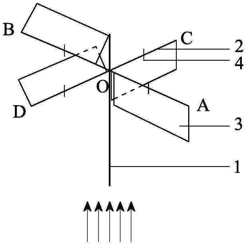
[0027] Such as figure 2 , Figure 4 As shown, a page wheel, O main wheel shaft 1, AO, BO, CO, DO are all main wheel arms 2, page plates 3 matching the number of the main wheel arms 2, the main wheel arms 2, etc. The angle is fixed on the main wheel shaft 1, and the main wheel arm 2 can rotate at any angle around the fixed point with the main wheel shaft 1 in the horizontal direction perpendicular to the axial direction of the main wheel shaft 1, that is, the wheel arm AO, BO, CO, DO can rotate 360° around the fixed point on the same plane. In this embodiment, a flat, thin, and hard rectangular plate is selected as the page plate 3, which is movably connected to the wheel arms AO, BO, CO, and DO respectively. The main wheel arm 2 is also provided with a retaining card 4, and the page Only the upper side edge of the panel 3 is connected to the main wheel arm 2, and the page plate 3 can rotate around the main wheel arm 2 within the range not blocked by the stop card 4, that is...
Embodiment 2
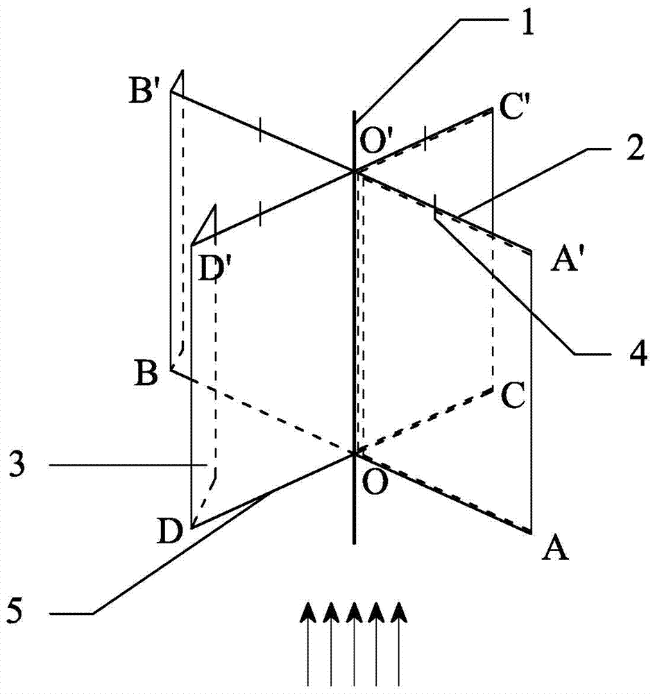
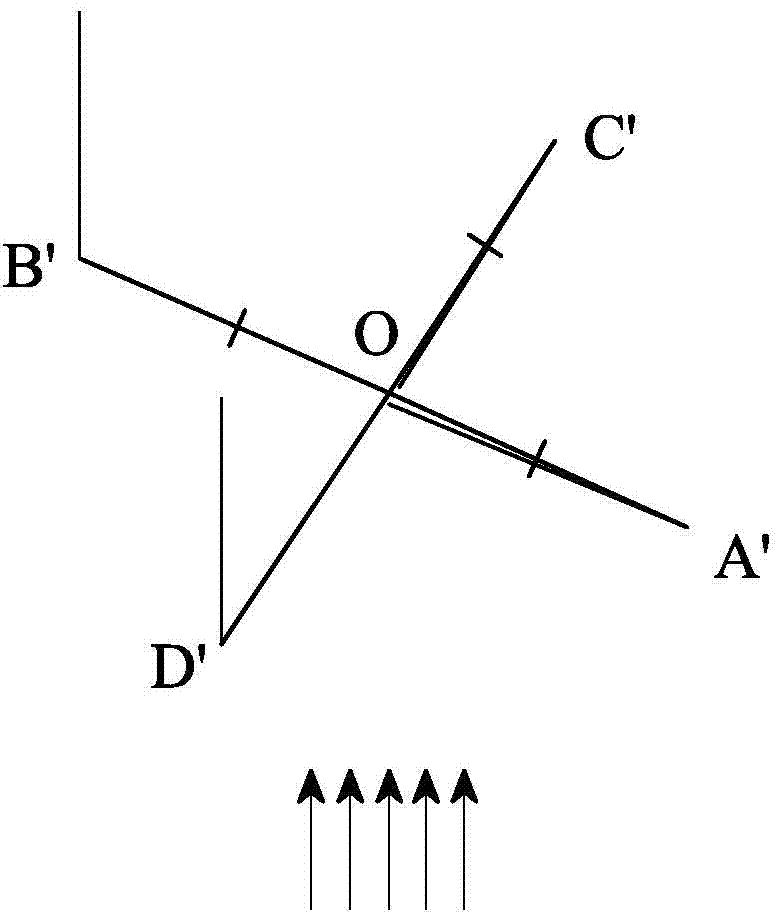
[0029] Such as figure 1 , image 3 As shown, a page wheel, OO' is the main wheel shaft 1, A'O', B'O', C'O', D'O' is the main wheel arm 2, AO, BO, CO, DO are the auxiliary wheels arm 5 and the page board 3 matched with the number of the main wheel arm 2, the number of the main wheel arm 2 and the auxiliary wheel arm 5 are equal and are respectively equiangularly fixed on the upper and lower ends of the main wheel shaft 1, the The main wheel arm 2 and the auxiliary wheel arm 5 can rotate at any angle around the fixed point with the main wheel shaft 1 in the horizontal direction perpendicular to the axial direction of the main wheel shaft 1. The shown main wheel arm 2 and the The auxiliary wheel arm 5, that is, the main wheel shaft 1 constitutes four accommodation frames for the rotation of the page board 3, and the main wheel arm 2 is also provided with a stopper 4 to constrain the page board 3 from driving beyond the wheel arm. noodle.
[0030] In this embodiment, the page ...
PUM
 Abstract
Description
Claims
Application Information
 - R&D Engineer
- R&D Manager
- IP Professional
- Industry Leading Data Capabilities
- Powerful AI technology
- Patent DNA Extraction
Browse by: Latest US Patents, China's latest patents, Technical Efficacy Thesaurus, Application Domain, Technology Topic, Popular Technical Reports.
© 2024 PatSnap. All rights reserved.Legal|Privacy policy|Modern Slavery Act Transparency Statement|Sitemap|About US| Contact US: help@patsnap.com