
DC power supply system and method of trolley locomotive of underground mine

A technology for power supply systems and electric locomotives, applied in power lines, vehicle components, transportation and packaging, etc., can solve problems such as automatic control system misoperation, small automatic system operating current, and life-threatening electric shock for workers to improve safety, The effect of preventing electric shock risk and simple structure

Active Publication Date: 2015-01-07
JIANGXI RARE EARTH & RARE METALS TUNGSTEN GRP HLDG CO LTD
View PDF7 Cites 0 Cited by
  • Summary
  • Abstract
  • Description
  • Claims
  • Application Information

AI Technical Summary

Problems solved by technology

The above-mentioned patents have the following deficiencies: (1) When the stringing length is large, in order to ensure the safety of stringing in different areas, it is necessary to set up no less than 2 parallel power supply lines (one line, one cable), and more than 2 patents Automatically controls the power-off device of the stringing wire, so the system structure is complex, the investment is large, and the maintenance and management are difficult; (2) When someone touches the stringing wire, its current is greater than the action current set by the automatic system (the lighting of the electric locomotive at 36V Current), the system automatically puts in the normal working voltage (such as 250V), and at this time workers will be in danger of electric shock; (3) When the electric locomotive is powered by a safe voltage of 36V or below, the lighting current is very small at the moment the electric locomotive is put in, and the setting of the automatic system The operating current is very small
Due to the humidity in the underground, there are many suspension points of the stringing wire, and its leakage current may cause the automatic control system to malfunction.

Method used


Image

  • DC power supply system and method of trolley locomotive of underground mine
  • DC power supply system and method of trolley locomotive of underground mine
  • DC power supply system and method of trolley locomotive of underground mine

Examples


Embodiment

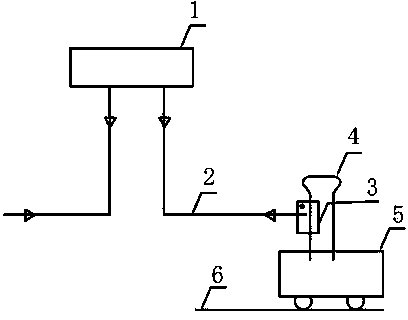
[0036] When the electric locomotive enters the roadway along the main road, the driver pulls down the pantograph of the electric locomotive, and connects the special power supply flexible cable and soft steel wire rope on the side of the roadway to the electric locomotive, and the electric locomotive takes power from the insulated trolley line. The driver drives the electric locomotive according to the normal driving method, and the electric locomotive automatically pulls the flexible cable to run back and forth. When the electric locomotive returns to the starting point and walks into the main transport road, the driver removes the special power supply flexible cable and reuses the pantograph of the electric locomotive itself to take power from the upper wire. The insulated trolley line of the power supply is in the state of insulation protection and no exposure, realizing full-length safe power supply, and there is no risk of electric shock.

[0037] The insulated trolley li...


PUM


Abstract

The invention relates to a DC power supply system and method of a trolley locomotive of an underground mine. The system comprises an insulated trolley conductor, the trolley locomotive, a trolley locomotive track, a pantograph, a flexible cable, a flexible steel wire rope and a connecting wire clamp; the flexible cable is fixed to the flexible steel wire rope; an insulating hole is arranged in the connecting wire clamp; the connecting wire clamp is arranged on the pantograph on the top part of the trolley locomotive and electrically connected with the pantograph; one end of the flexible cable is connected with the power supply of the trolley conductor, and while the other end of the flexible cable is connected with the pantograph through the connecting wire clamp; one end of the flexible steel wire rope is fixed to an insulated connecting component of an electricity taking guide line of the trolley conductor, and while the other end of the flexible steel wire rope is hung on the insulating hole of the connecting wire clamp. The power supply system is simple in structure, small in investment, and convenient to maintain; a power wire is kept in an insulated, protected and exposing-free state, thus full-length safe power supply can be realized, and the risk of electric shock can be avoided.

Description

technical field [0001] The invention relates to a power supply system for a wire electric locomotive, in particular to a DC power supply system and method for a wire electric locomotive along a roadway in a metal and nonmetal underground mine. Background technique [0002] The power supply method of the existing DC trolley locomotive is to use the exposed trolley wire (bare trolley line) suspended in the roadway along the vein near the center of the roof as the positive pole, and the transportation track as the negative pole of the DC power supply. Get DC power. Due to the short and narrow roadways along the veins of underground mines, this power supply method has a greater risk of electric shock safety, and there is a risk that the wiring will not be able to transmit power normally due to leakage. The strung wire near the center of the roof hinders the normal operation of the miner. Safety regulations for metal and non-metal mines (GB l6423-2006) stipulates that for th...

Claims


Application Information

Patent Timeline
Patent Type & Authority Applications(China)
IPC IPC(8): B60M3/00
Inventor 严正斌
Owner JIANGXI RARE EARTH & RARE METALS TUNGSTEN GRP HLDG CO LTD
Learn More