An electric discharge machining device

A processing device and electric spark technology, applied in electric processing equipment, accessories, metal processing equipment, etc., can solve problems such as increased cost, prolonged production process, and cumbersome process.

Active Publication Date: 2016-01-20
TANGSHAN ZHENGFENG IRON & STEEL CO LTD
View PDF6 Cites 0 Cited by
  • Summary
  • Abstract
  • Description
  • Claims
  • Application Information

AI Technical Summary

Problems solved by technology

However, for workpieces with combined and complex structural requirements for the cavity structure, frequent replacement of forming tool electrodes is required, resulting in the disadvantages of prolonged production process, cumbersome process and increased cost

Method used


Image

  • An electric discharge machining device
  • An electric discharge machining device
  • An electric discharge machining device

Examples


Embodiment Construction

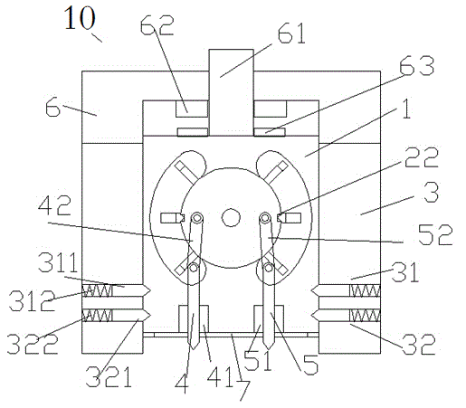
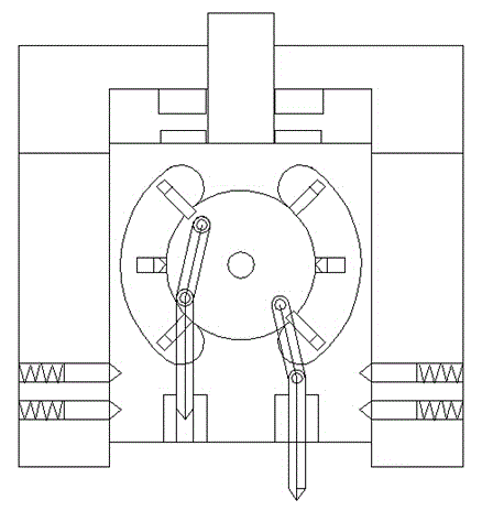
[0028] Refer below Figure 1-5 , describe the present invention in detail.

[0029] An electric discharge machining device, which includes an electric discharge machining head 10, a lifting device 101, a column 102, a workbench 103, a workpiece 105, and a processing medium supply device 104, wherein the lifting device 101 can move up and down along the column 102 so that Lifting and lowering the EDM head 10, the worktable 103 carries the processing medium supply device 104, the workpiece 105 is placed in the processing medium in the processing medium supply device 104,

[0030] Described electrical discharge machining head 10 comprises lower frame 3, upper frame 6 and inner frame 1, and described upper frame 6 is above described lower frame 3, and inner frame 1 is positioned at by lower frame 3 and inner frame 1. In the chamber formed by the upper frame 6, and can slide up and down;

[0031]Wherein, the upper inner side of the upper frame 6 and the upper side of the inner fr...


PUM


Abstract

Disclosed is an electrosparking device which comprises an electrosparking head (10), a lifting device (101), an upright (102), a workbench (103), a workpiece (105) and a machining medium supplying device (104). The lifting device (101) can move up and down along the upright (102) to raise and lower the electrosparking head (10), the machining medium supplying device (104) is borne on the workbench (103), and the workpiece (105) is disposed in a machining medium in the machining medium supplying device (104).

Description

technical field [0001] The invention relates to the field of electric discharge machining, in particular to an electric discharge machining device. Background technique [0002] EDM is a special processing method that uses the electric erosion effect generated by the pulse discharge between the two electrodes immersed in the working fluid to erode conductive materials, also known as electric discharge machining or electric erosion machining. [0003] During EDM, the tool electrode and the workpiece are respectively connected to the two poles of the pulse power supply, and immersed in the working fluid, or the working fluid is filled into the discharge gap. The tool electrode is controlled to feed to the workpiece through the gap automatic control system. When the gap between the two electrodes reaches a certain distance, the pulse voltage applied to the two electrodes will break down the working fluid and generate spark discharge. A large amount of heat energy is concentrat...

Claims


Application Information

Patent Timeline
Patent Type & Authority Patents(China)
IPC IPC(8): B23H1/00B23H1/04B23H7/26
CPCB23H1/00B23H1/04B23H11/00B23H2400/00
Inventor 张康
Owner TANGSHAN ZHENGFENG IRON & STEEL CO LTD
Why Eureka
Try Eureka