
A multi-connected horizontal vacuum fryer

A technology of vacuum frying machine and horizontal oil, which is applied in the direction of oil/fat baking, etc., which can solve the problems of complex supporting facilities, increased pipeline resistance, and low processing efficiency, so as to achieve high facility utilization, prolong the service life, and improve The effect of work efficiency

Active Publication Date: 2017-07-11
XUZHOU XUSHU SHUYE TECH
View PDF10 Cites 0 Cited by
  • Summary
  • Abstract
  • Description
  • Claims
  • Application Information

AI Technical Summary

Problems solved by technology

Regardless of the built-in heating type or the external heating type, it is basically one pot, one system, and the supporting facilities of each system are very complicated, the investment cost is relatively high, the waste of resources is serious, the production capacity is small, and the work efficiency is low, so it is difficult to form mass production
[0003] The built-in vacuum fryer is heated by the steam jacket at the bottom of the pot body, which belongs to static heating, and its heating speed is slow, and it is easy to affect the quality of fried food due to local overheating; at the same time, the basket needs to be inside the pot when entering and exiting. Moving up and down, the operation process is troublesome, and the cycle of each frying is also long, so that the processing efficiency is very low
The external heating fryer has fast heating speed, simple operation process, short frying cycle, and high production efficiency. However, the conventional external heating fryer can only fry one fryer in one frying cycle. Single frying pan works, but multiple frying single frying pans cannot work at the same time. In addition, the heating and filtering devices of these external heating frying pans are all set on the connecting pipeline, which not only increases the resistance on the pipeline, but also During the frying process, it is easy to generate air chambers on the pipeline, which will cause the oil to cut off and affect the cycle and effect of frying

Method used


Image

  • A multi-connected horizontal vacuum fryer
  • A multi-connected horizontal vacuum fryer

Examples


Embodiment Construction

[0013] The present invention will be further described below in conjunction with accompanying drawing.

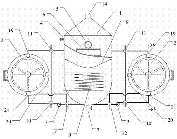
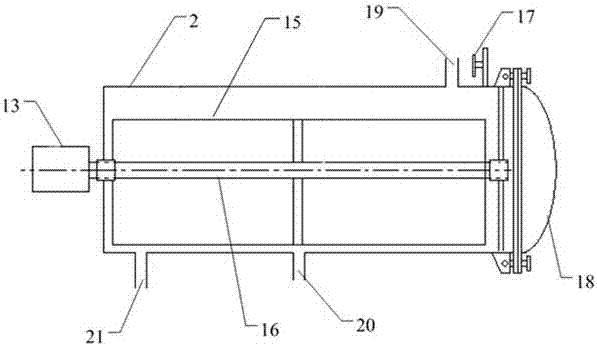
[0014] like Figure 1 to Figure 2 As shown, a multi-connected horizontal vacuum fryer includes a motor 13, a horizontal fryer 2, an oil pump 3, and an oil tank 1. One end of the horizontal fryer 2 is provided with a motor 13, and the other end is provided with a A pot cover 18, the top of the horizontal fryer 2 is provided with a pot body exhaust valve 17, and a material basket 15 is arranged inside it, and a shaft 16 is connected in the middle of the material basket 15, and the shaft 16 is connected to the shaft of the motor 13. connection, the top of the oil tank 1 is connected to the vacuum device through the vacuum system interface 14, the upper part of the tank body of the oil tank 1 is provided with an exhaust valve 4 and a slag outlet 6, and the bottom end is provided with a discharge valve 7 The tank body of the oil tank 1 is provided with a filtering device 8 and ...


PUM


Abstract

The invention discloses a parallel horizontal vacuum frying machine. The top end of an oil tank (1) is connected with a vacuumizing device, a tank body of the oil tank (1) is provided with an exhaust valve (4), a slag outlet (6) and a discharging valve (7), a filtering device (8) and a heating device (9) are arranged in the tank body of the oil tank (1), upper-portion oil outlets (19) of at least two horizontal fryers (2) are connected with the upper portion of the oil tank (1) while lower-portion oil inlets (21) of the same are connected with third three-way valves (12) sequentially through first three-way valves (10) and oil pumps (3), the third three-way valves (12) are connected with the lower portion of the oil tank (1) and lower-portion oil outlets (20) of the horizontal fryers (2) respectively, and second three-way valves (11) and the first three-way valves (10) are communicated through pipelines. The parallel horizontal vacuum frying machine enables multiple fryers to work at the same time to realize system sharing, so that production efficiency can be improved greatly.

Description

technical field [0001] The invention relates to a vacuum frying device, in particular to a multi-connected horizontal vacuum frying machine. Background technique [0002] At present, the structure of vacuum fryers at home and abroad is similar, and they all belong to an integrated machine that integrates frying, oil storage, vacuum, and heating, or is called a stand-alone machine. In production applications, there are two types of vacuum fryers: built-in heating type and external heating type. Regardless of the built-in heating type or the external heating type, it is basically one pot, one system, and the supporting facilities of each system are very complicated, the investment cost is relatively high, the waste of resources is serious, the production capacity is small, and the work efficiency is low, so it is difficult to form Large-scale production. [0003] The built-in vacuum fryer is heated by the steam jacket at the bottom of the pot body, which belongs to static he...

Claims


Application Information

Patent Timeline
Patent Type & Authority Patents(China)
IPC IPC(8): A21B5/08
CPCA21B5/08
Inventor 徐飞金辉袁起李勇
Owner XUZHOU XUSHU SHUYE TECH
Learn More