submersible generator

A submersible and generator technology, applied in hydroelectric power generation, ocean energy power generation, engine components, etc., to achieve the effect of suppressing the increase in rotation speed

Active Publication Date: 2016-09-28
KYOWA ENG CONSULTANTS
View PDF13 Cites 0 Cited by
  • Summary
  • Abstract
  • Description
  • Claims
  • Application Information

AI Technical Summary

Problems solved by technology

Therefore, in the above-mentioned submersible generator in which the opposite outer rotating armature and inner fixed armature are independently arranged, in order to obtain a high starting voltage or to obtain high electrical efficiency, it is necessary to install a speed increasing gear or The pulley mechanism transmits the rotation speed of the propeller to the outer rotating armature, leading to an increase in the size of the generator

Method used


Image

  • submersible generator
  • submersible generator
  • submersible generator

Examples


Embodiment Construction

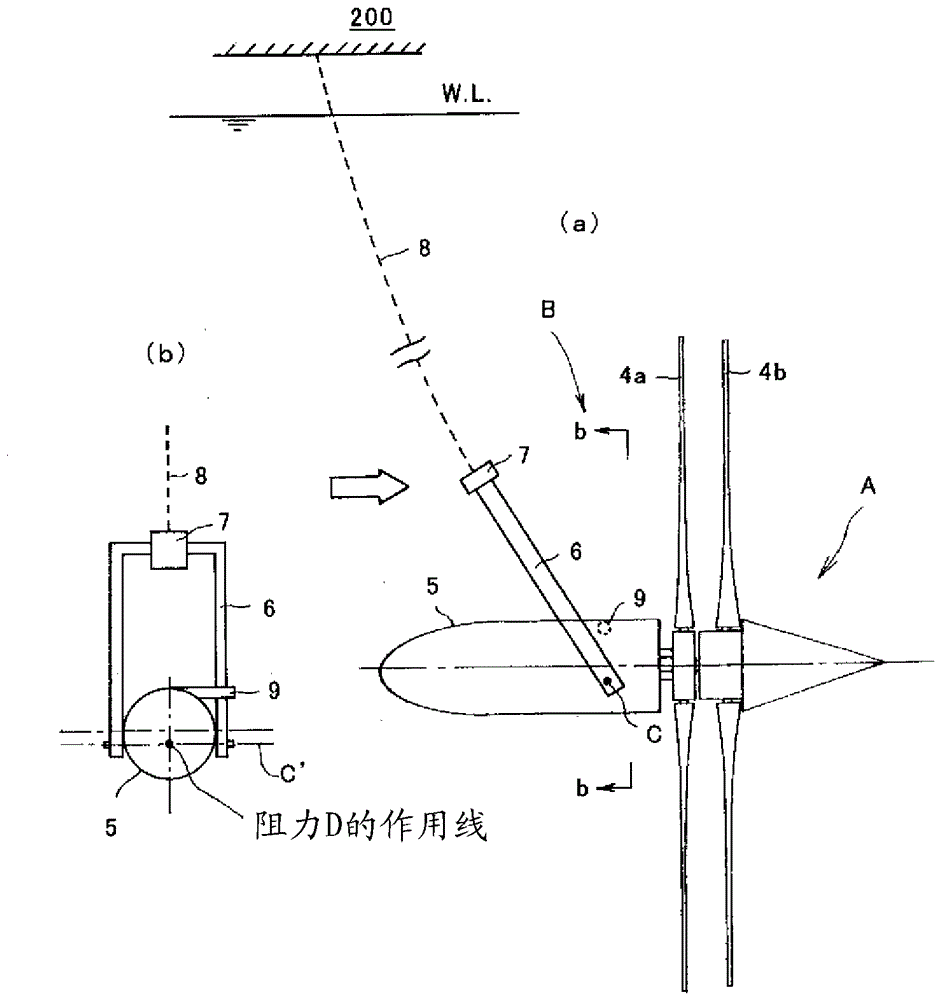
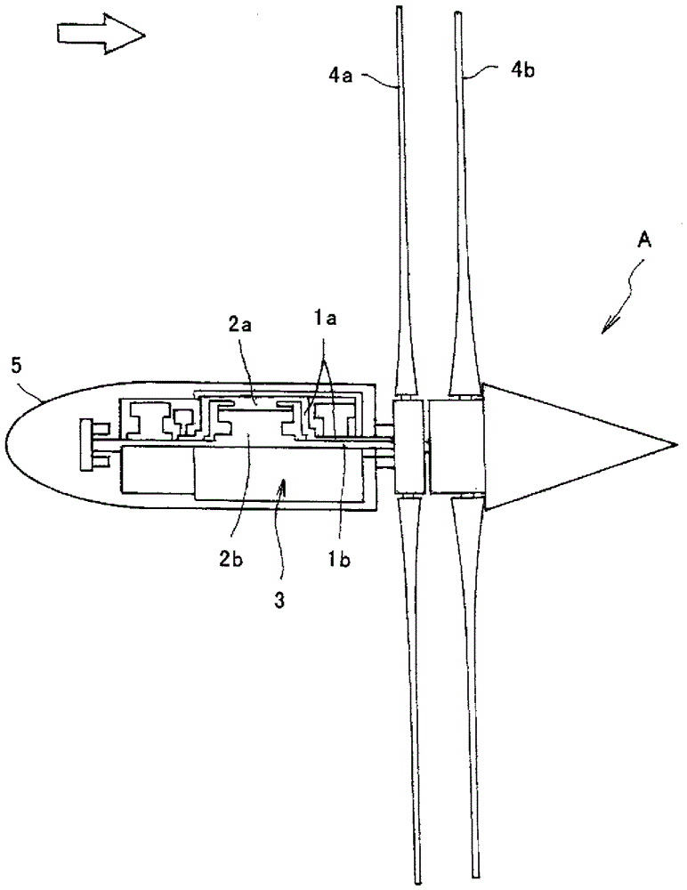
[0043] A submersible generator and a submersible power generation system according to an embodiment of the present invention will be described.

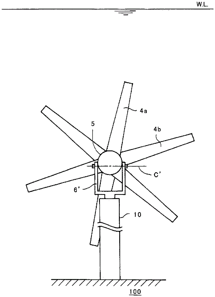
[0044] Such as figure 1 As shown, the submersible generator A has an inner and outer double-layer rotating armature generator mechanism 3, a front-stage propeller 4a, a rear-stage propeller 4b, and a shell 5 in the shape of a cannonball, wherein the inner and outer double-layer rotating armature generator mechanism 3 It has a cylindrical outer shaft 1a, an inner shaft 1b inserted into the outer shaft 1a so that the axis center is consistent, an outer rotating armature 2a fixed on the outer shaft 1a, and an outer rotating armature 2a fixed on the inner shaft 1b and facing the outer rotating armature 2a. The inner rotating armature 2b, the front stage propeller 4a is fixed on the outer shaft 1a and drives the outer shaft 1a, and then drives the outer rotating armature 2a to rotate, and the rear stage propeller 4b is figure 1 The direc...


PUM


Abstract

[Object of the Invention] An object of the present invention is to provide a submersible power generator which can be stably moored in water and can generate high electromotive voltage and achieve high power generation efficiency without being increased in size. [Disclosure of the Invention] A submersible power generator comprising relatively rotating inner and outer armatures, propellers for driving the inner and outer armatures to rotate relative to each other, and a casing for accommodating the inner and outer armatures, which submersible power generator comprises an inner / outer double rotational armatures-type power generation mechanism provided with an outer rotational armature and an inner rotational armature opposing the outer rotational armature to rotate in a direction opposite to a direction of rotation of the outer rotational armature, and a pair of propellers disposed coaxially with blades of one of the pair of propellers and blades of the other of the pair of propellers twisted in opposite directions relative to an extending direction of a central axis of the pair of propellers, wherein one of the propellers is connected to one of the inner and outer rotational armatures and the other of the propellers is connected to the other of the inner and outer rotational armatures, and further comprises a casing for accommodating the inner / outer double rotational armatures-type power generation mechanism and shielding it from an external environment, and which submersible power generator, as installed under water to operate in a water current, is made to have gravity W acting thereon which is larger than buoyancy F acting thereon during operation of the submersible power generator, and which, as seen on a meridian plane (a vertical plane including a rotational axis of the propellers), makes a rotational moment center, around which a sum total of rotational moments generated by gravity W acting thereon, buoyancy F acting thereon and drag D acting thereon in a water current becomes zero, come to be located on the casing.

Description

technical field [0001] The present invention relates to submersible generators. Background technique [0002] Patent Document 1 discloses a submersible generator equipped with relatively rotating inner and outer armatures, a propeller that drives the inner and outer armatures to rotate relatively, and a housing for accommodating the armatures. The power generation mechanism of the armature and the inner fixed armature rotates in opposite directions, drives the front and rear two-stage outer rotating armatures to rotate the front and rear two-stage propellers in opposite directions, and drives the front and rear two-stage inner fixed motors to rotate in opposite directions. The shell that is airtightly accommodated by the pivot relative to the external environment is connected to the anchor placed on the bottom of the water via a mooring cable, and is placed in the water flow in a submerged state to work. The buoyancy acting on the submersible generator is greater than that a...

Claims


Application Information

Patent Timeline
Patent Type & Authority Patents(China)
IPC IPC(8): F03B13/26
CPCF03B13/10F03B13/105F03B13/264F03B17/061F05B2240/97F05B2250/311Y02E10/30Y02E10/20
Inventor 金元敏明左村公
Owner KYOWA ENG CONSULTANTS
Why Eureka
Try Eureka