
Carbon brush mounting structure, motor and motor assembling method

A technology of installation structure and carbon brush, which is applied in the manufacture of motor generators, electrical components, electromechanical devices, etc., can solve the problems of unfavorable automatic production of motors, low production efficiency, unreasonable installation structure design of motors, etc., to achieve automatic production, Improve production efficiency and achieve the effect of installation and fixation

Inactive Publication Date: 2014-12-24
GUANGDONG WELLING ELECTRIC MACHINE MFG
View PDF6 Cites 3 Cited by
  • Summary
  • Abstract
  • Description
  • Claims
  • Application Information

AI Technical Summary

Problems solved by technology

[0004] The purpose of the present invention is to overcome the deficiencies of the prior art above, and provide a carbon brush installation structure, a motor with the installation structure, and an assembly method for the motor, which aims to solve the problems caused by the unreasonable design of the existing carbon brush installation structure. Low motor production efficiency and technical problems that are not conducive to automatic production of motors

Method used


Image

  • Carbon brush mounting structure, motor and motor assembling method
  • Carbon brush mounting structure, motor and motor assembling method
  • Carbon brush mounting structure, motor and motor assembling method

Examples


Embodiment Construction

[0023] In order to make the object, technical solution and advantages of the present invention clearer, the present invention will be further described in detail below in conjunction with the accompanying drawings and embodiments. It should be understood that the specific embodiments described here are only used to explain the present invention, not to limit the present invention.

[0024] It should be noted that when an element is described as being “fixed” or “disposed on” another element, it may be directly on the other element or there may be an intervening element at the same time. When an element is described as being "connected to" another element, it can be directly connected to the other element or intervening elements may also be present.

[0025] It should also be noted that the orientation terms such as up, down, top, and bottom in this embodiment are only relative concepts or refer to the normal use state of the product, and should not be regarded as limiting.

...


PUM


Abstract

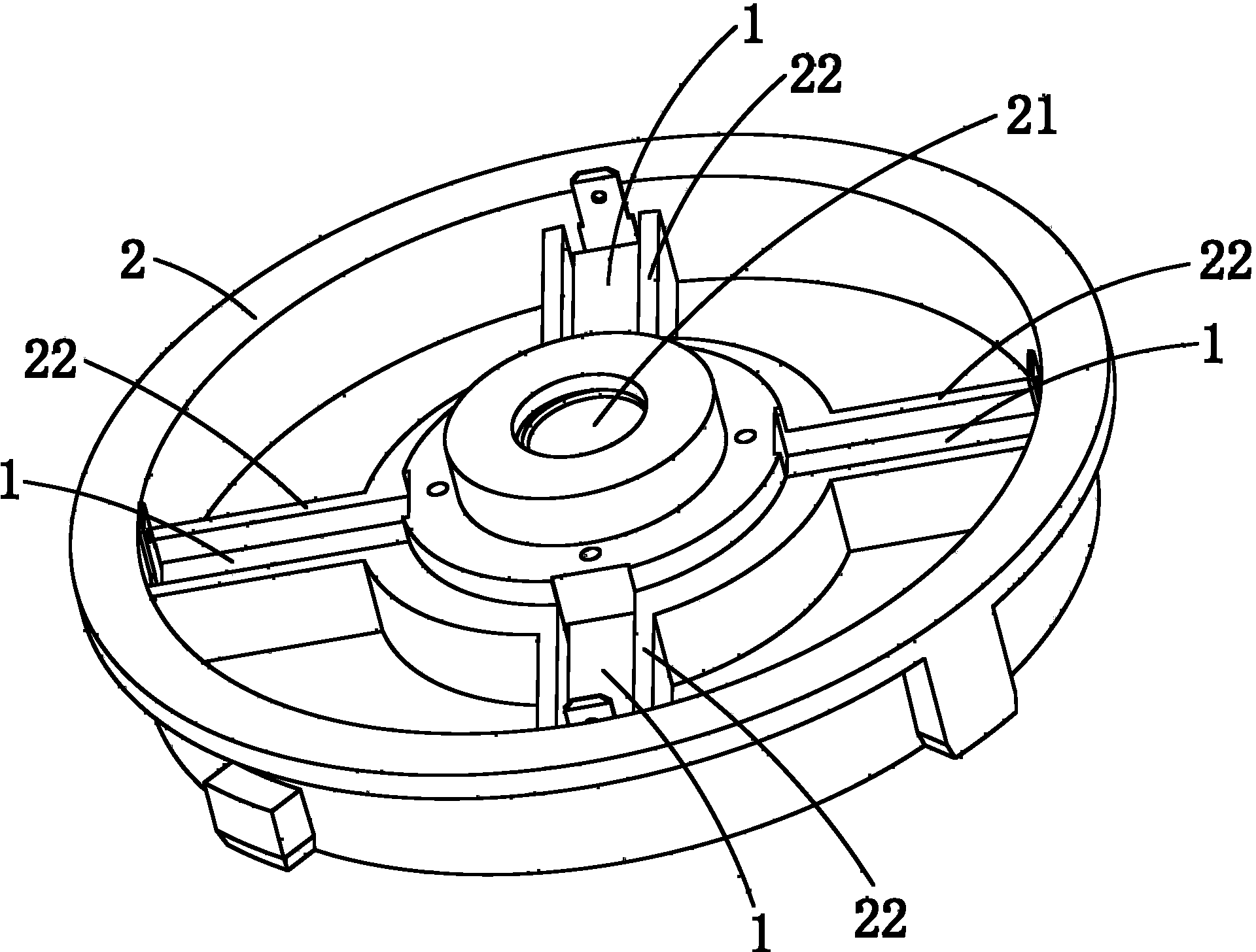
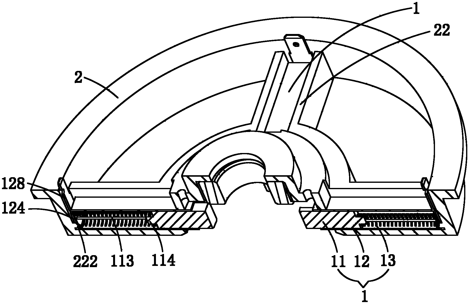
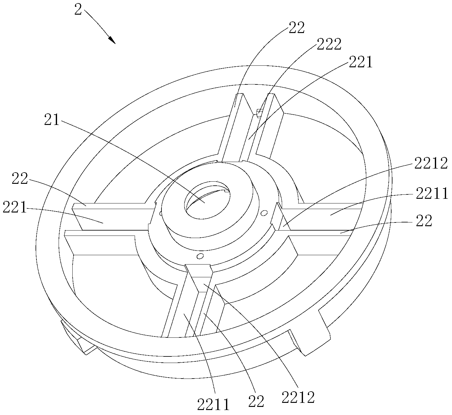
The invention belongs to the field of motors, and discloses a carbon brush mounting structure, a motor with the mounting structure and a motor assembling method. The carbon brush mounting structure comprises carbon brushes, brush sleeves, elastic pieces and an end cover. The end cover is provided with axle holes and brush racks. The carbon brushes are mounted in the brush sleeves in a sliding mode through the elastic pieces so that carbon brush assemblies can be formed. The brush racks are provided with opening grooves which are matched with the brush sleeves, the opening grooves are provided with axial mounting openings and radial openings which are communicated with the axle holes, and the carbon brush assemblies are inserted into the opening grooves in a clamping mode from the axial mounting openings in the axial direction of the end cover. One end of each carbon brush extends into the corresponding axle hole from one radial opening. According to the carbon brush mounting structure, the motor and the motor assembling method, each carbon brush assembly is mounted on the end cover in the clamping insertion mode in the axial direction of the end cover, in the specific production process, after the end cover and an armature are assembled, then the electric brush assemblies are mounted on the end cover, so that the interference phenomenon of the carbon brushes and a commutator is avoided in the assembling process of the electric brushes and the end cover, the assembling efficiency of the end cover and the armature is improved, and thus the production efficiency of the motor is improved ultimately.

Description

technical field [0001] The invention belongs to the field of motors, and in particular relates to a carbon brush installation structure, a motor with the installation structure, and an assembly method of the motor. Background technique [0002] In the prior art, the installation structure of the carbon brush of the motor generally includes a carbon brush, a copper sleeve, a spring, an insulating sleeve and an end cover. The end cover is provided with a brush holder, wherein the copper sleeve is fixed on the brush holder by riveting. The carbon brush and spring are installed in the copper sleeve, and the carbon brush and the copper sleeve are generally connected by riveting first, and then wrapped and insulated with insulating materials, and the insulating sleeve is set on the lead wire of the carbon brush. [0003] In the existing motor with the installation structure of the above-mentioned carbon brush, the carbon brush can only be installed on the end cover along the radia...

Claims


Application Information

Patent Timeline
Patent Type & Authority Applications(China)
IPC IPC(8): H02K5/14H02K15/14
Inventor 梁显堂玉国成段有钦胡松坡韦强立
Owner GUANGDONG WELLING ELECTRIC MACHINE MFG
Learn More