
An electronic device and power supply method

A technology of electronic equipment and power supply module, which is applied in the electronic field, can solve the problems of high manufacturing cost of electronic equipment, achieve the effects of reducing occupied space, saving manufacturing cost, and preventing damage

Active Publication Date: 2018-12-14
LENOVO (BEIJING) LTD
View PDF6 Cites 0 Cited by
  • Summary
  • Abstract
  • Description
  • Claims
  • Application Information

AI Technical Summary

Problems solved by technology

[0006] Embodiments of the present invention provide an electronic device and a power supply method, which are used to solve the technical problem of high manufacturing cost of electronic devices in the prior art

Method used


Image

  • An electronic device and power supply method
  • An electronic device and power supply method
  • An electronic device and power supply method

Examples


Embodiment 1

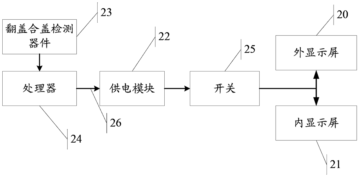
[0088] In this embodiment, the electronic device will be introduced as an example of a flip phone, please refer to figure 2 , the flip phone includes an outer display screen 20 (i.e. the first functional module), an inner display screen 21 (i.e. the second functional module), and the operating voltage of the outer display screen 20 is 1.8V (i.e. the first voltage), The operating voltage of the inner display screen 21 is 2.8V (i.e. the second voltage). Since, under normal circumstances, flip phones are in an unused state, that is, in a closed state, so under normal circumstances, the outer display screen 20 is in the In the working state, the initialization voltage of the power supply module 22 for supplying power to the outer display screen 20 and the inner display screen 21 is 1.8V.

[0089] Wherein, at time T1, user A controls the flip phone to be in the flip state, and the flip and lid detection device 23 of the flip phone detects that the flip phone is switched from the l...

Embodiment 2

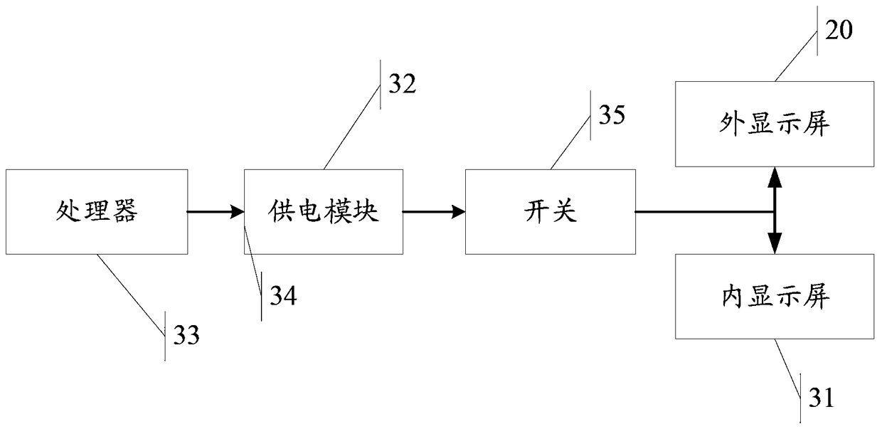
[0096] In this embodiment, the electronic device will be described as a bar mobile phone as an example, please refer to image 3 , the bar computer includes a front camera 30 (that is, the first functional module), a rear camera 31 (that is, the second functional module), and the operating voltage of the front camera 30 is 1.8V (that is, the first voltage), The operating voltage of the rear camera is 2.8V (i.e. the second voltage), because usually, users use the rear camera to work, so it is used to supply power to the front camera 30 and the rear camera 31 The initialization voltage of the power supply module 32 is 2.8V, which is used to supply power to the rear camera 31.

[0097] At time T3, user B starts the camera of the straight mobile phone to take a selfie. Since the rear camera 31 of the straight mobile phone is in working condition, it needs to be switched to the front camera 30. User B clicks a button on the straight mobile phone. A preset button, after the candy b...


PUM


Abstract

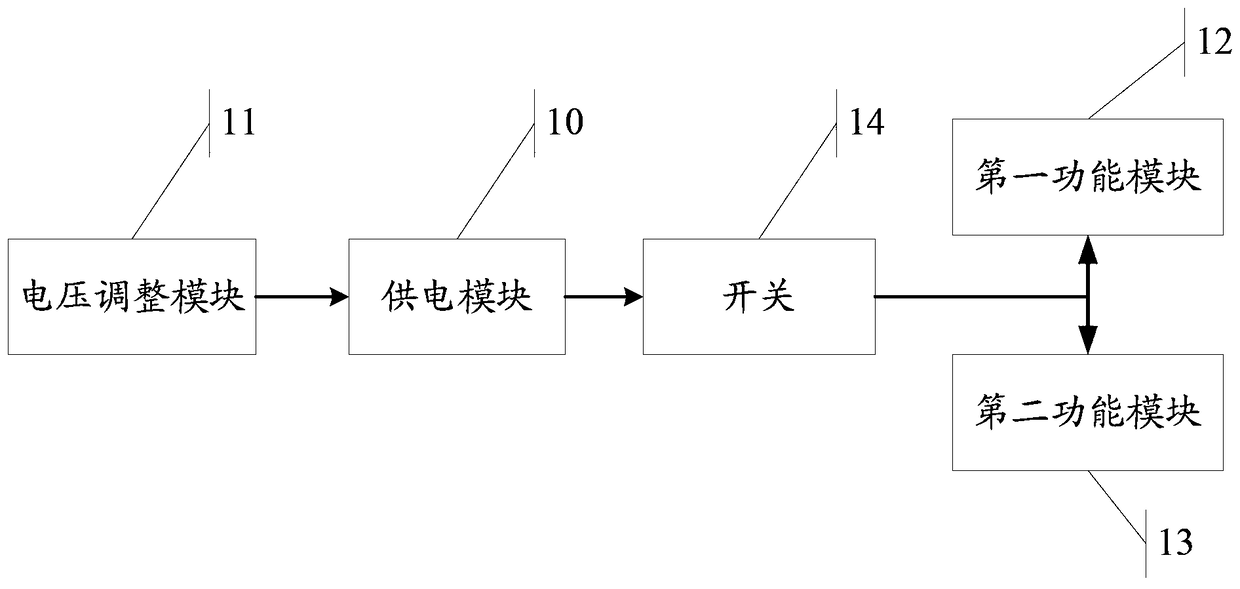
The invention relates to the technical field of electrons and discloses electronic equipment and a power supplying method with an aim to solve the technical problem that electronic equipment in the prior art is high in manufacturing cost. The electronic equipment comprises a power supply module, a voltage regulating module, a first function module and a second function module, the voltage regulating module is connected with the power supply module and used for regulating the size of output voltage of the power supply module, the first function module adopts first voltage to work, and the second function module adopts second voltage different from the first voltage to work; when the first function module is at the working state, the voltage regulating module controls the output voltage to be the first voltage which is supplied to the first function module; when the second function module is at the working state, the voltage regulating module controls the output voltage to be the second voltage which is supplied to the second function module. Since the number of the power supply modules is reduced, the technical effect of cost reduction is achieved.

Description

technical field [0001] The invention relates to the field of electronic technology, in particular to an electronic device and a power supply method. Background technique [0002] With the continuous development of science and technology, electronic technology has also been developed rapidly, and more and more electronic devices have been produced, such as mobile phones, tablet computers, notebook computers and so on. Now people can enjoy the comfortable life brought by the development of science and technology through various types of electronic devices. [0003] Usually, electronic equipment contains different devices, such as: front camera, rear camera, external display, internal display, etc. These devices may need to work with different voltages, such as: front camera The operating voltage of the device is 1.8V, the operating voltage of the rear camera is 2.8V, etc. In order to ensure that these devices can work normally, in the prior art, different power supply chips a...

Claims


Application Information

Patent Timeline
Patent Type & Authority Patents(China)
IPC IPC(8): G06F1/26
Inventor 单文英宋以祥林金强
Owner LENOVO (BEIJING) LTD
Learn More