Wear-resistant reciprocating grate support structure

A support structure and reciprocating furnace technology, which is applied in the field of boiler grate, can solve the problems of short service life of grate pieces, blockage of grate pieces, decreased combustion efficiency, etc., and achieve the effects of reducing maintenance costs, improving use efficiency, and improving combustion efficiency

Active Publication Date: 2016-10-12
JINAN BOILER GRP
View PDF6 Cites 0 Cited by
  • Summary
  • Abstract
  • Description
  • Claims
  • Application Information

AI Technical Summary

Problems solved by technology

There are various defects in the structure of the traditional reciprocating grate. First, the working conditions of the reciprocating grate are poor, and there is relative movement between the grates. Due to the influence of the high-temperature fuel layer, the grate pieces are prone to jamming and deformation. The mutual wear between the fixed grate and the movable grate makes the service life of the grate short and needs to be replaced frequently, which increases the maintenance cost and time of the boiler and reduces the running time of the boiler. In order to prolong the service life, the user has to replace the boiler The grate is made very thick to prolong the wear time and reduce the shutdown time of the boiler; second, the installation accuracy of the grate is low, and the gap between the grate is uneven, resulting in coal leakage and blockage of the ventilation hole, resulting in poor ventilation and resulting in fuel The combustion is uneven, and in some places the combustion is not sufficient, and the combustion efficiency decreases

Method used


Image

  • Wear-resistant reciprocating grate support structure
  • Wear-resistant reciprocating grate support structure
  • Wear-resistant reciprocating grate support structure

Examples


Embodiment Construction

[0016] The present invention will be further described below through non-limiting embodiments and in conjunction with the accompanying drawings.

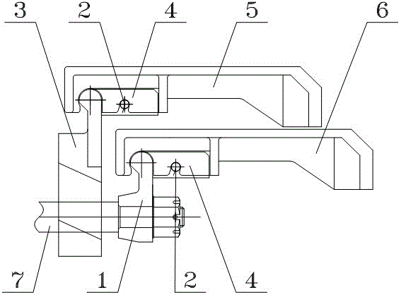
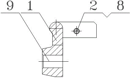
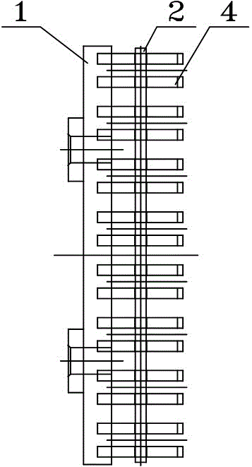
[0017] Such as Figure 1 to Figure 7 As shown, a wear-resistant reciprocating grate support structure includes movable grate 6, fixed grate 5, movable shelf 1 and fixed shelf 3, and the movable shelf is provided with a connecting hole 9, which is connected with Pull rod 7, pull rod 7 is connected with movable fire grate driving mechanism, movable fire grate piece 6 and fixed fire grate piece 5 are clamped on movable shelf 1 and fixed shelf 3 respectively through the card slot 12 thereon, after connection, movable furnace A gap of 3mm is reserved between the top and bottom of the row piece and the fixed grate piece; the positioning plate group corresponding to the movable fire grate piece 6 is fixedly connected to the movable shelf 1, and the positioning plate group is composed of two positioning plates 4, two The distance between t...


PUM


Abstract

The invention discloses an anti-wear reciprocating fire grate supporting structure. The movable grate piece and the fixed grate piece are clamped on the movable shelf and the fixed shelf respectively, and the movable shelf and the fixed shelf are connected with a positioning plate set corresponding to the fire grate piece, and the two positioning plate sets of the positioning plate set The distance between them is slightly greater than the thickness of the grate ribs; the ribs of the grate can be inserted between the two positioning plates, which can prevent the movable or fixed grate from moving left and right, so as to keep the gap between the grate even and not As for the phenomenon of poor ventilation caused by coal leakage and blockage of ventilation holes, the combustion of fuel is more uniform and sufficient, thereby improving combustion efficiency. The movable grate and the fixed grate are respectively supported by separate support rods to prevent wear and friction between the movable grate and the fixed grate, improve the service life of the reciprocating grate, reduce the number of shutdowns of the boiler, and reduce the boiler The maintenance cost is reduced, and the efficiency of the boiler is improved.

Description

technical field [0001] The invention relates to a boiler fire grate, in particular to a boiler reciprocating fire grate device. Background technique [0002] The grate is a component that stacks solid fuel in a boiler or an industrial furnace and makes it burn effectively. The fixed grate piece and the movable grate piece are stacked at intervals to form a stepped grate surface, and the fuel moves on the grate surface. Its function is to gradually transport the fuel blocks falling from the silo to the slag discharge port, and make them fully burn during the transport process. There are various defects in the structure of the traditional reciprocating grate. First, the working conditions of the reciprocating grate are poor, and there is relative movement between the grates. Due to the influence of the high-temperature fuel layer, the grate pieces are prone to jamming and deformation. The mutual wear between the fixed grate and the movable grate makes the service life of the ...

Claims


Application Information

Patent Timeline
Patent Type & Authority Patents(China)
IPC IPC(8): F23H11/18F23H17/08
Inventor 刘作王海峰胡安全刘旭
Owner JINAN BOILER GRP
Why Eureka
Try Eureka