
Ignition detection device and method for automobile

An automobile, ignition voltage technology, applied in the direction of engine ignition, spark ignition controller, engine components, etc., can solve the problems of heavy load on power-consuming batteries and the failure of vehicles to start normally, so as to reduce power consumption and prolong service life Effect

Active Publication Date: 2014-12-24
DALIAN ROILAND SCI & TECH CO LTD
View PDF5 Cites 15 Cited by
  • Summary
  • Abstract
  • Description
  • Claims
  • Application Information

AI Technical Summary

Problems solved by technology

[0002] At present, the power supply methods of electronic products in automobiles mainly include two methods. When the car is ignited, the motor supplies power to it, and when the car is not ignited, the battery supplies power to it. With the development of the automobile industry, automotive electronic products are increasing day by day. When the car is in the unignited state, if it is only for the electronic equipment in the car to supply power, the excessive power consumption will cause a large burden on the battery, and even cause the vehicle to fail to start normally. Therefore, the electronic equipment in the vehicle is not ignited. The state should be in a low power consumption state, such as entering a dormant or sleeping state. In this state, the user should reduce the use of electronic equipment in the car, which requires the user to know in advance whether the vehicle is in the ignition state.

Method used


Image

  • Ignition detection device and method for automobile
  • Ignition detection device and method for automobile

Examples


Embodiment

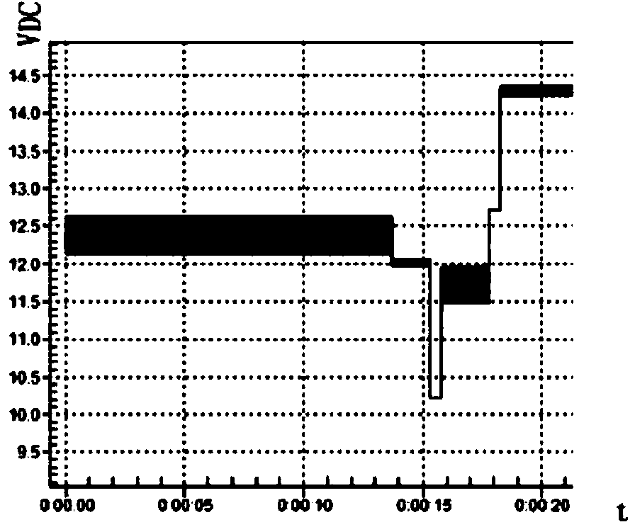
[0027] When the ignition action of the car occurs, the output voltage of the battery is lower than the stable output voltage of the battery because the spark plug and the electrical equipment consume electricity at the same time. The output voltage of the accumulator rises and is higher than 12V, that is, the accumulator is in the ignition voltage state of the vehicle during the secondary interval of the time interval when the accumulator outputs low voltage.

[0028] When the car is ignited, since the engine starts to work, the engine will enter the state of engine idling from a static state. When the vehicle is idling, the engine will vibrate during the period, which is also an ignition state prompt.

[0029] Based on the above enlightenment, this embodiment provides a method for automobile ignition detection, such as figure 1 As shown, the steps are as follows:

[0030] S1. Detect the real-time voltage output by the battery, and input the real-time voltage value output by ...


PUM


Abstract

The invention discloses an ignition detection device and an ignition detection method for an automobile. The method comprises the following steps: S1, detecting real-time voltage output by a storage battery; S2, if a vibration sensor detects a vibration signal, recording vibration signal information; S3, outputting low voltage which is lower than the voltage stably output by the storage battery at a certain time interval by an MCU (Microprogrammed Control Unit) processor; S4, judging the primary time interval of the real-time voltage output by the storage battery in the time interval of the low voltage is in the ignition voltage state of the automobile or not; S5, judging whether a recorded vibration signal of which the generation time interval is comprised in the time interval in which the real-time voltage output by the storage battery is in the ignition voltage state of the automobile exists or not, and judging that ignition operation is performed on the automobile if the vibration signal information exists. By adopting the ignition detection device and the ignition detection method for the automobile provided by the invention, a user can judge the ignition state of the automobile, so that the use of electronic equipment in a vehicle can be reduced consciously when the vehicle is in a non-ignition state, the power consumption of the storage battery is lowered, and the service life of the storage battery is prolonged.

Description

technical field [0001] The invention relates to a detection device and method, in particular to an automobile ignition detection device and method. Background technique [0002] At present, the power supply methods of electronic products in automobiles mainly include two methods. When the car is ignited, the motor supplies power to it, and when the car is not ignited, the battery supplies power to it. With the development of the automobile industry, automotive electronic products are increasing day by day. When the car is in the unignited state, if it is only for the electronic equipment in the car to supply power, the excessive power consumption will cause a large burden on the battery, and even cause the vehicle to fail to start normally. Therefore, the electronic equipment in the vehicle is not ignited. The state should be in a low power consumption state, such as entering a dormant or sleep state. In this state, the user should reduce the use of electronic equipment in t...

Claims


Application Information

Patent Timeline
Patent Type & Authority Applications(China)
IPC IPC(8): F02P17/00
Inventor 田雨农苍柏李宝王强
Owner DALIAN ROILAND SCI & TECH CO LTD
Learn More