A Ring-by-Ring Lifting Installation Method of Suspension Dome Cable-strut System

An installation method and a technology for a dome with chord support, which can be applied to buildings and building structures, etc., can solve the problems of high crane performance requirements, high construction measures, and difficulty in deploying cables, so as to reduce the amount of work at heights and reduce requirements. The effect of working difficulty and easy connection

Active Publication Date: 2016-08-24
SOUTHEAST UNIV
View PDF5 Cites 0 Cited by
  • Summary
  • Abstract
  • Description
  • Claims
  • Application Information

AI Technical Summary

Problems solved by technology

[0003] The conventional construction and installation method of the suspension dome is the full hall support method, that is, the full hall support is set up under the upper reticulated shell as an operation platform for the upper reticulated shell and the lower cable-strut system to be assembled at high altitude, and bears the self-weight and construction load of the components, such as the Jinan Olympic Sports Center This method is traditional and simple for gymnasiums, Changzhou Gymnasium and Beijing University of Technology Gymnasium and other suspension dome structures, but the weight of the full support often exceeds the weight of the suspension dome structure itself, the construction measures are expensive, the construction period is long, and the coiled cables Hoisting to the high-altitude support requires high performance of the crane and it is difficult to deploy the cables. The high formwork occupies the ground space for a long time, and it also has a large safety risk.

Method used


Image

  • A Ring-by-Ring Lifting Installation Method of Suspension Dome Cable-strut System
  • A Ring-by-Ring Lifting Installation Method of Suspension Dome Cable-strut System
  • A Ring-by-Ring Lifting Installation Method of Suspension Dome Cable-strut System

Examples


Embodiment Construction

[0032] The technical solution of the present invention will be described in detail below in conjunction with the accompanying drawings.

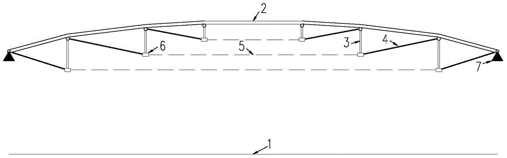
[0033] Such as figure 1 As shown, a kind of suspension dome cable-strut system of the present invention hoists and installs method ring by ring, comprising the following steps:

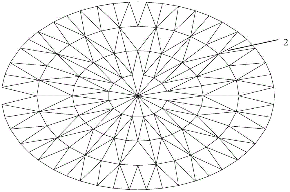
[0034] The first step: install the supporting tower 8 of the upper reticulated shell 2, hoist the upper reticulated shell 2 on the supporting tower 8 in pieces, and assemble to form the upper reticulated shell 2 as a whole; the upper reticulated shell 2 is equipped with connecting node. In the first step, the boundary of the assembled upper reticulated shell 2 is supported by the structural support 7 .

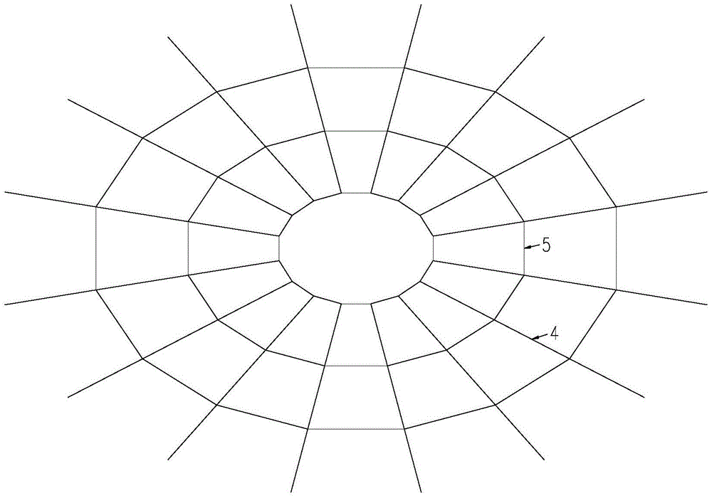
[0035] Step 2: Make the cables and transport them to the construction site, unfold the loop cables 5 on the projection ground 1 ring by ring, install the cable clips 6, the struts 3 and the oblique cables 4, and then use the tooling connector 9 to connect the str...


PUM


Abstract

The invention discloses a ring-by-ring lifting and installation method of the cable-strut system of a suspensive dome, which includes the following steps: the first step: hoisting the upper reticulated shell to the supporting tower in blocks to form the whole upper reticulated shell; the second step: step by step The hoop is unfolded on the projected ground, and the cable clips, struts and oblique cables are installed, and then the upper end of the strut and the upper end of the oblique cable are connected by tooling connectors to assemble a cable rod lifting unit; the third step: the upper net The shell is a lifting platform, and the lifting equipment is arranged ring by ring on the lifting platform, and the lifting equipment is connected to the upper end of the strut through the lifting cable; the fourth step: use the lifting equipment to lift the lifting unit of the cable rod ring by ring, and then use the ball joint or The pin shaft connects the upper reticulated shell with the upper end of the strut, as well as the upper reticulated shell and the upper end of the cable; Step 5: Remove the lifting equipment, hoisting rope and tooling connectors. The installation method can reduce the amount of brackets in the construction of the suspend dome structure, facilitate the assembly of the cable-strut system, reduce the installation cost, shorten the construction period and improve the construction efficiency.

Description

technical field [0001] The invention belongs to the technical field of cable structure construction in civil engineering engineering, and in particular relates to a ring-by-ring lifting installation method of a cable-strut system of a suspensive dome. Background technique [0002] Suspension dome structure is a reasonable new long-span space structure combining reticulated shell and cable dome structure. A space combination structure, in which the cable-rod system includes braces, oblique cables and ring cables. Suspension dome is a prestressed self-balancing structure. Compared with the reticulated shell structure, it has the advantages of good overall stability, light weight, small support thrust, and strong spanning ability. Therefore, it has been applied in many large-scale stadium roof structures in China. [0003] The conventional construction and installation method of the suspension dome is the full hall support method, that is, the full hall support is set up under...

Claims


Application Information

Patent Timeline
Patent Type & Authority Patents(China)
IPC IPC(8): E04B1/35
Inventor 罗斌田伟郭正兴
Owner SOUTHEAST UNIV
Why Eureka
Try Eureka