
Manipulator device for motor stator assembly

A motor stator and manipulator technology, applied in the field of manipulators, can solve the problems of unbalanced lifting, damage, safety hazards, etc., and achieve the effects of improving work efficiency, convenient and flexible operation, and reducing labor load.

Inactive Publication Date: 2014-12-24
盐城市昱博汽车零部件有限公司
View PDF0 Cites 8 Cited by
  • Summary
  • Abstract
  • Description
  • Claims
  • Application Information

AI Technical Summary

Problems solved by technology

When the motor stator is moved or installed, it is generally necessary to manually lift the stator, use a wire rope to pass through the bottom of the stator, and then use a loader or a crane to lift it, but this will easily lead to unbalanced lifting, and due to the large mass of the stator, manual operation is not easy Control, a little carelessness will cause the stator to collide and cause damage
There are also many safety hazards in manual operation, which brings a lot of inconvenience to the installation, especially for large motors, which cannot be operated manually
The technicians of scientific research units and enterprises are constantly exploring and researching, hoping to develop a manipulator device with convenient operation and superior performance, which can be used for the assembly of motor stators, so as to ensure the safety of operators and improve production efficiency. progress, but there are still technical difficulties that have not been overcome in practical application

Method used


Image

  • Manipulator device for motor stator assembly
  • Manipulator device for motor stator assembly

Examples


Embodiment Construction

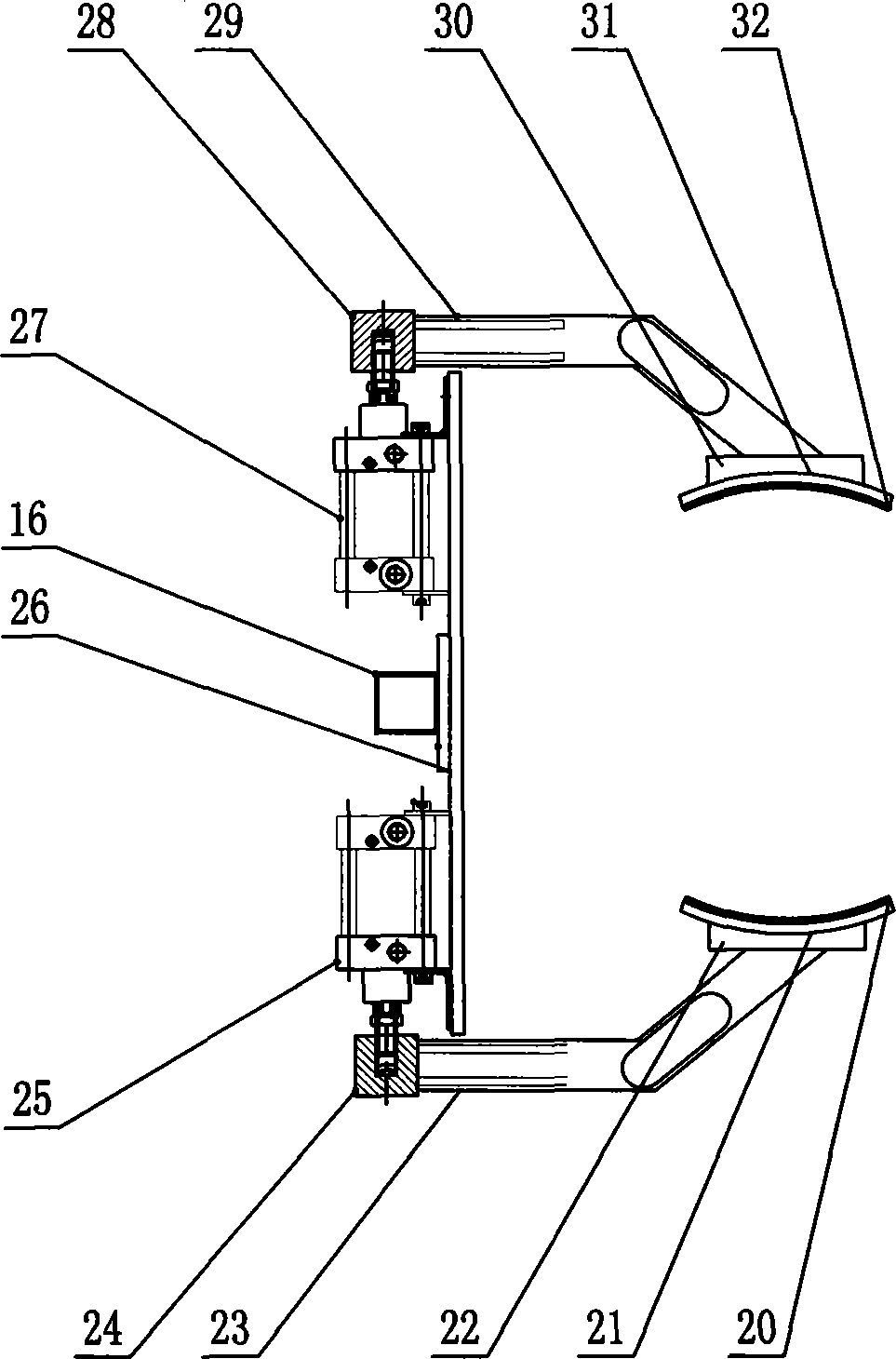
[0012] exist figure 1 , 2 Among them, the bottom plate 1 is fixed on the ground through expansion bolts, the middle part of the bottom plate 1 is provided with a column 2, and the top of the column 2 is provided with a main rotating seat 4, which can rotate 360°. The main rotating seat 4 is connected to the large side plate 7 through the main rotating shaft 5 connection, the large side plate 7 is provided with an air pressure control valve, the air pressure control valve is connected with the telescopic cylinder 3, the left lower end of the large side plate 7 is provided with a telescopic cylinder 3, and the guide rod is connected with the guide sleeve at the lower end of the small side plate 6, The big side plate 7 is provided with the small side plate 6, and the left side of the big side plate 7 is provided with a long strip waist-shaped hole sliding shaft groove, and two sliding shafts are arranged in the shaft groove, one is up and the other is divided, and the two sliding...


PUM


Abstract

The invention belongs to a manipulator and relates to a manipulator device used for motor stator assembly. A bottom plate is fixed on the ground through expansion bolts. A vertical post is arranged at the center of the bottom plate. A main rotating seat is arranged at the top end of the vertical post. The main rotating seat is connected with a large side plate through a main rotating shaft. A telescopic cylinder is arranged at the lower end of the left side of the large side plate. A small side plate is arranged on the large side plate. One end of a main rocking arm and one end of an auxiliary rocking arm are both connected with the large side plate; the other end of the main rocking arm and the other end of the auxiliary rocking arm are both connected with a connecting plate. A cross arm rotating seat is connected with a rotating arm through a rotating arm spindle. The cross arm rotating seat is connected with the rotating arm spindle. The rotating arm is connected with a vertical arm rotating seat which is connected with an auxiliary rotating shaft. The auxiliary rotating shaft is connected with a lower vertical arm. A rotating cylinder is arranged at the tail end of the lower vertical arm. A spindle of the rotating cylinder is connected with a clamping cylinder of a fixture. The manipulator device allows an operator to easily perform procedures, such as carrying, turning and assembling a stator, while barely feeling the weight; the manipulator device is simple and easy to operate, efficient and safe.

Description

technical field [0001] The invention relates to a manipulator, in particular to a manipulator device for assembling motor stators, which is suitable for the motor assembling industry of elevators. Background technique [0002] Since the reform and opening up, the national economy has grown rapidly, "scientific and technological innovation, independent innovation" has become the mainstream of domestic industrial development, and my country's industry is gradually developing in the direction of intensive, energy-saving, emission-reducing, and low-carbon. As a means of transportation in the vertical direction, elevators have become important construction equipment and are indispensable in high-rise buildings and public places. With the development of computer technology and power electronics technology, modern elevators have become typical mechatronic products. The elevator has high safety requirements. It leaves the factory in the form of parts, and the final assembly is carr...

Claims


Application Information

Patent Timeline
Patent Type & Authority Applications(China)
IPC IPC(8): B25J9/04B25J9/14B25J13/00B25J15/08
Inventor 王三祥
Owner 盐城市昱博汽车零部件有限公司
Learn More