Interpolated three-dimensional thermal dose estimates using magnetic resonance imaging

A technology for magnetic resonance imaging and thermal dose estimation, which is applied in the directions of using nuclear magnetic resonance imaging systems for measurement, magnetic resonance measurement, and magnetic variable measurement, and can solve problems such as anisotropy and low resolution.

Inactive Publication Date: 2014-12-17
KONINKLIJKE PHILIPS NV
View PDF4 Cites 6 Cited by
  • Summary
  • Abstract
  • Description
  • Claims
  • Application Information

AI Technical Summary

Problems solved by technology

The measurements can also be 3D, e.g. for 3D MR imaging, but if so the resolution is typically low and anisotropic to allow real-time acquisition

Method used


Image

  • Interpolated three-dimensional thermal dose estimates using magnetic resonance imaging
  • Interpolated three-dimensional thermal dose estimates using magnetic resonance imaging
  • Interpolated three-dimensional thermal dose estimates using magnetic resonance imaging

Examples


Embodiment Construction

[0147] The same reference numbers in these figures either designate equivalent elements or perform the same function. Elements that have been discussed previously will not necessarily be discussed in subsequent figures if they are functionally equivalent.

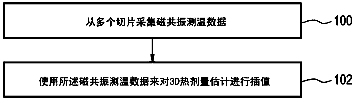
[0148] figure 1 A flowchart illustrating a method according to an embodiment of the invention is shown. In step 100, magnetic resonance thermometry data is acquired from a plurality of slices. Next in step 102, the three-dimensional thermal dose estimation is interpolated using the magnetic resonance thermometry data.

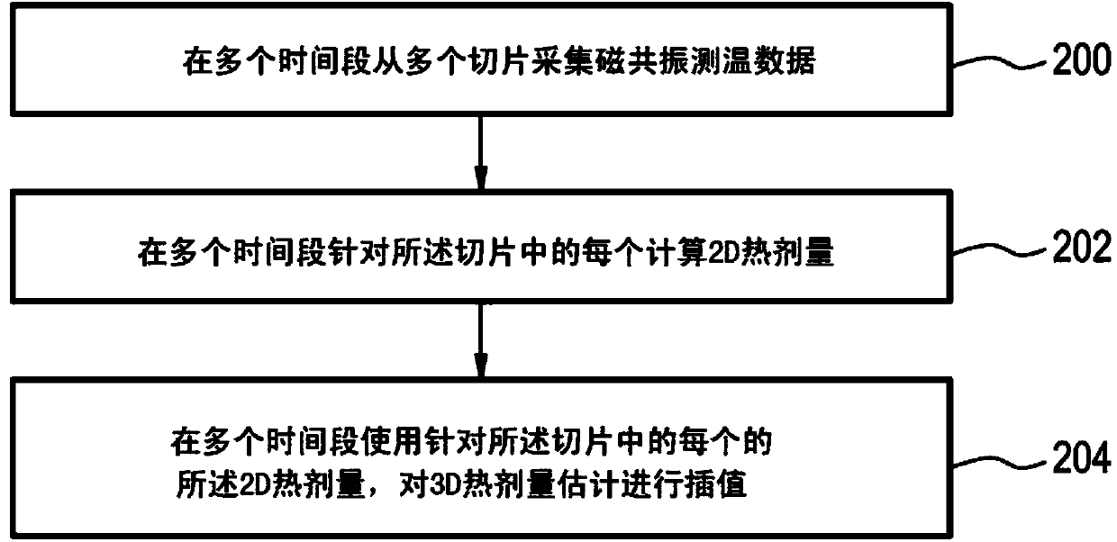
[0149] figure 2 A flowchart illustrating a method according to a further embodiment of the invention is shown. In step 200, magnetic resonance thermometry data is acquired from a plurality of slices. Next in step 202 a thermal dose estimate is calculated for each of the slices over a plurality of time periods. Next in step 204, the 3D thermal dose estimate is interpolated over a plurality of time peri...


PUM


Abstract

The invention provides for a medical apparatus (400, 500, 600, 700, 800) comprising a magnetic resonance imaging system (402) for acquiring magnetic resonance thermometry data (442) from a subject (418). The magnetic resonance imaging system comprises a magnet (404) with an imaging zone (408). The medical apparatus further comprises a memory (432) for storing machine executable instructions (460, 462, 464, 466, 10, 660). The medical apparatus further comprises a processor (426) for controlling the medical apparatus, wherein execution of the machine executable instructions causes the processor to: acquire (100, 200, 300) the magnetic resonance thermometry data from multiple slices (421, 421', 421'') within the imaging zone by controlling the magnetic resonance imaging system; and interpolate (102, 202, 204, 302, 304) a three dimensional thermal dose estimate (444) in accordance with the magnetic resonance thermometry data.

Description

technical field [0001] The present invention relates to magnetic resonance imaging, and more particularly to the use of magnetic resonance imaging for the estimation of three-dimensional thermal dose. Background technique [0002] Thermal dose is a measure of thermal tissue damage that is based on the Arrhenius equation and was originally introduced by Sapareto and Dewey in 1984 and is given by: [0003] TD ( t ) = ∫ 0 t R 43 - T ( τ ) dτ [0004] in [0005] R = 0.25 , T ≤ 43 0.5 ...

Claims


Application Information

Patent Timeline
Patent Type & Authority Applications(China)
IPC IPC(8): G01R33/48
CPCG01R33/4804G01R33/4814G01R33/48A61B5/015A61B5/055G01R33/30G01R33/31
Inventor M·O·科勒
Owner KONINKLIJKE PHILIPS NV
Why Eureka
Try Eureka