
Power steering system

A technology of power steering device and steering wheel, applied in power steering mechanism, steering mechanism, steering rod and other directions, can solve the problems of increased vehicle weight, waste of fuel, high price, etc., to prevent slippage, meet mechanical needs, and have a simple structure Effect

Inactive Publication Date: 2014-12-17
朴永孝
View PDF8 Cites 3 Cited by
  • Summary
  • Abstract
  • Description
  • Claims
  • Application Information

AI Technical Summary

Problems solved by technology

[0013] Agricultural tractors are equipped with a double-speed steering system in order to double the rotation of the outer wheel of the rear axle when turning. However, the double-speed steering system is expensive, which will increase the price of agricultural tractors and increase the weight of the vehicle, resulting in waste of fuel. more serious problems

Method used


Image

  • Power steering system
  • Power steering system
  • Power steering system

Examples


Embodiment Construction

[0038] The structure of the present invention will be described in detail below in conjunction with the accompanying drawings.

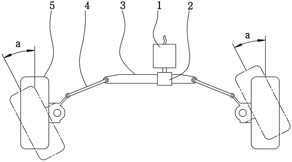
[0039] The structure of the present invention is to combine the running body 101 of the steering tube 105 with the support shaft 106 of the support rod 111 to rotate by the power transmitted to the steering tube 105 through the drive part and the gear box with the operation of the steering wheel;

[0040] With the rotation of the running body 101, the wheel housing 115 combined with the flow shaft 114 through the guide pipes 113 on both sides of the support plate 112 is rotated to adjust the angle of the wheel 116, and one end is rotatably connected to the running body 101 through the connecting shaft 102. The other end is rotatably combined with the two side pull rods 103 and

[0041] On the running body 101, the connecting shafts 102 on both sides combined with the tie rods 103 on both sides are symmetrically combined on the left and right around t...


PUM


Abstract

The present invention relates to a steering apparatus. Specifically, the provided power steering apparatus couples a steering pipe formed on a driving body as a supporting shaft of a base member to rotate the steering pipe by the driving force which is caused by the operation of the steering handle and is delivered to the steering pipe through a driving unit and a gear box, and includes a tie rod on either sides with an end coupled to the driving unit to be easily rotated by the connection shaft and another end coupled to a wheel housing be easily rotated to by the center shaft to rotate the wheel housing which couples the moving shaft to guide pipes on either sides of the supporting plate by the rotation of the driving unit.

Description

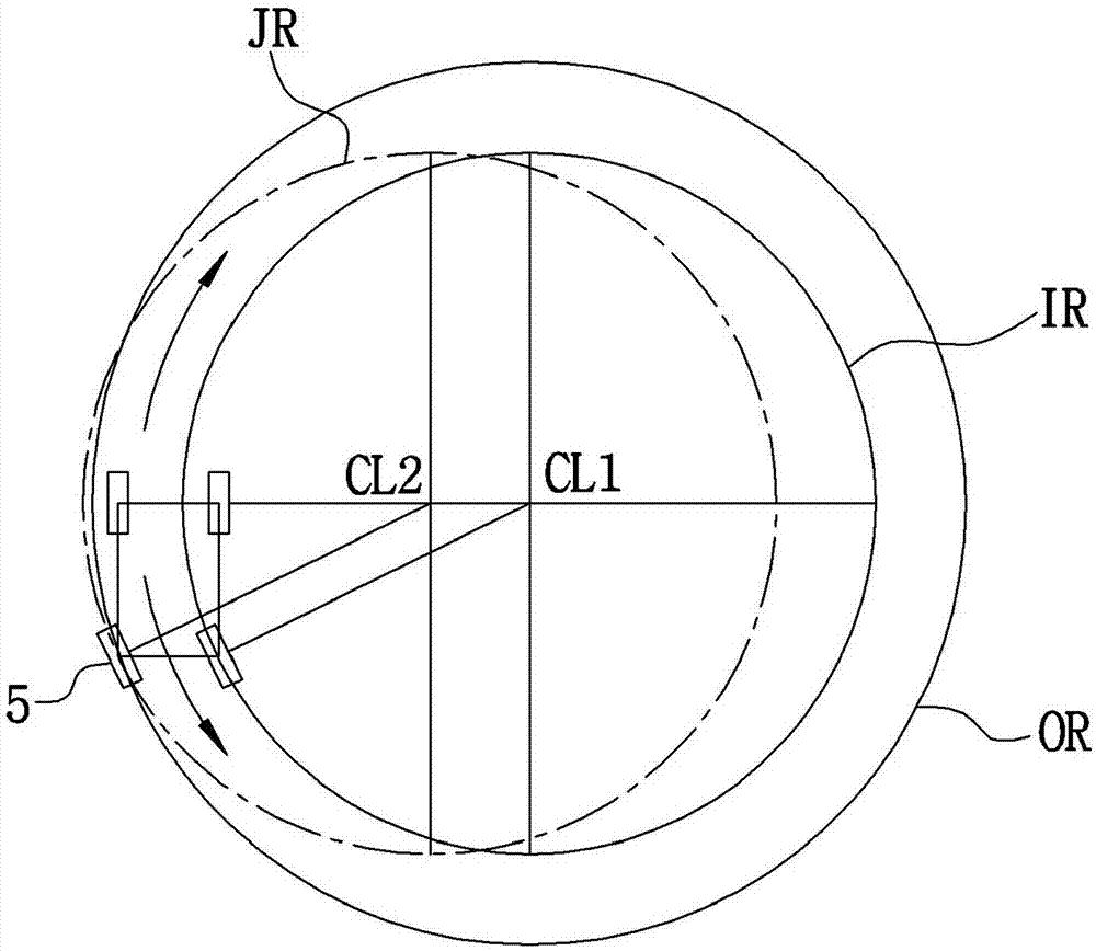
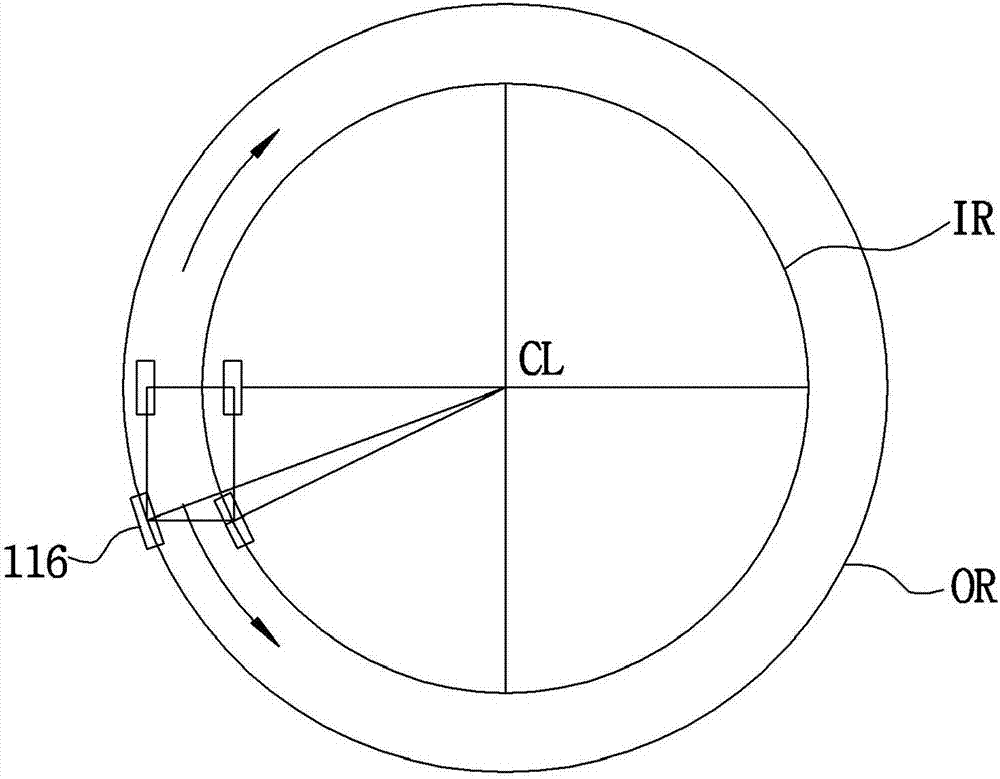
Technical field [0001] The present invention involves the steering device. It is specifically through the steering tube formed by the supporting shaft of the supporting rod. The operation of the steering wheel is transmitted to the power rotation of the steering tube through the driver and the gear box.The axis can rotate the upper body, and the other end can be combined with the two -sided tie rods that can be rotated through the central axis and wheels shell. It can rotate with the rotation of the rotation body to rotate the wheel shell on both sides of the support plate binding to the flow shaft shell.The angle of adjusting the wheels; and turning to the inner wheels that turn to the inner wheels in the direction of circling direction when driving on the curve, turning the small inner trajectory while rotating, the outer wheel is rotated at a smaller angle, and the large outer trajectory is drawn at a smaller angle.This prevents the inner wheel from slipping, blocking the vibra...

Claims


Application Information

Patent Timeline
Patent Type & Authority Applications(China)
IPC IPC(8): B62D7/16
CPCB62D3/02B62D5/0415B62D7/08B62D7/16
Inventor 朴永孝
Owner 朴永孝
Learn More