
Railway passenger train body and railway vehicle

A technology for railway passenger cars and car bodies, applied in the direction of railway roofs and other directions, can solve problems such as inconvenience, low efficiency, and inconvenient operation, and achieve the effects of convenient maintenance, improved assembly efficiency, and convenient operation.

Active Publication Date: 2014-12-17
CRRC TANGSHAN CO LTD
View PDF5 Cites 17 Cited by
  • Summary
  • Abstract
  • Description
  • Claims
  • Application Information

AI Technical Summary

Problems solved by technology

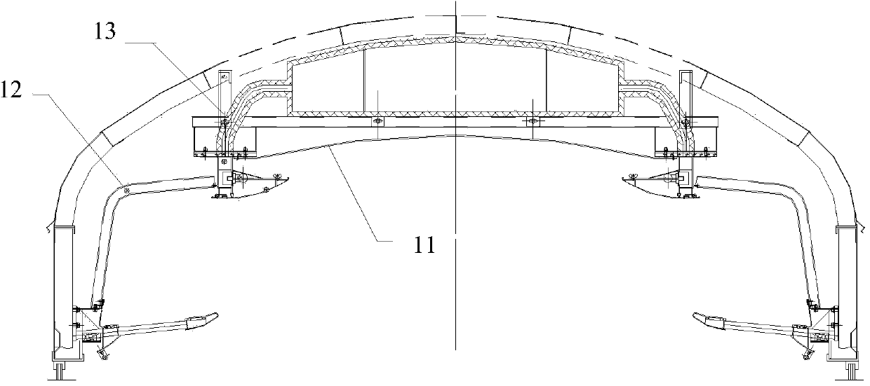
Wherein, the middle top board 11 comprises a plurality, and is arranged in sequence along the longitudinal direction, and correspondingly, the side top board 12 also includes a plurality of longitudinally arranged ones, each middle top board 11 and side top board 12 edges are respectively provided with inserting parts, and adjacent Between the middle top boards 11, between the adjacent side top boards 12, and between the adjacent middle top boards 11 and the side top boards 12 are connected through the above-mentioned specific matching plug-in parts, so that when installing, it is necessary to strictly follow the construction The process installs the middle roof, side roof and related accessories one by one, which is inconvenient to operate and low in efficiency; in addition, in the follow-up maintenance process, the middle roof or side roof cannot be removed separately, so the entire inner roof inside the car body needs to be removed. Repair and maintenance can only be carried out after dismantling, which is very inconvenient

Method used


Image

  • Railway passenger train body and railway vehicle
  • Railway passenger train body and railway vehicle
  • Railway passenger train body and railway vehicle

Examples


Embodiment Construction

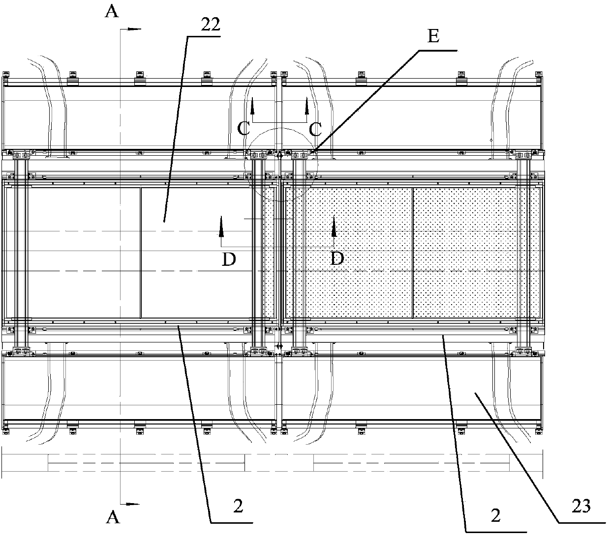
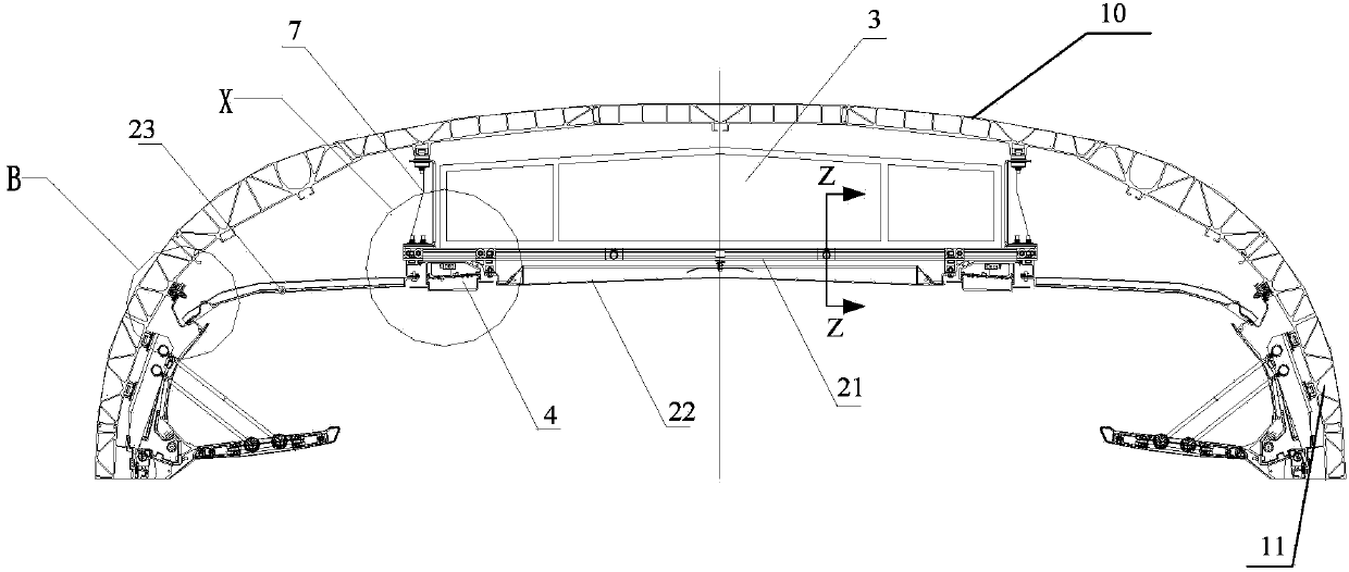
[0017] figure 2 It is a top view of the inner top plate in the railway passenger car body of the present invention; image 3 for figure 2 A-A sectional view; Figure 4 for figure 2 Middle D-D direction view; Figure 5 for figure 2 Middle C-C direction view; please refer to Figure 2-5 , the present embodiment provides a railway passenger car body, including a car body steel structure. At least two inner roof assemblies 2 arranged longitudinally; the inner roof assembly 2 includes: a skeleton 21, a middle roof 22, and side roofs 23 located on both sides of the middle roof 22; the skeleton 2 is fixedly connected to the inner surface of the roof 10 of the vehicle body; the skeleton It includes at least two longitudinally extending longitudinal beams 211 and at least two crossbeams 212 fixedly connected between the two longitudinal beams 211, the middle top plate 22 is covered under the frame 21, and the two sides are respectively fixedly connected to the two longitudina...


PUM


Abstract

The invention provides a railway passenger train body and a railway vehicle. The train body comprises a train body steel structure, wherein the train body steel structure comprises train body side walls and a train body top part, the inner side of the train body top part is provided with at least two inner top plate assemblies in the longitudinal direction, each inner top plate assembly comprises a skeleton, a middle top plate and side top plates, the side top plates are respectively positioned at the two sides of each middle top plate, the skeleton comprises at least two longitudinal beams and at least two transverse beams, each middle top plate covers under the skeleton, the two sides of each middle top plate are respectively and fixedly connected with the two longitudinal beams, the butting part of the middle top plates of the two adjacent top plate assemblies is provided with a gap blocking cover plate which is used for blocking a gap between the middle top plates, the two ends of the gap blocking cover plate are respectively and fixedly connected with the two longitudinal beams, one side, facing the skeleton, of each side top plate is respectively and fixedly connected with the corresponding longitudinal beam, and the other side of each side top plate is fixedly connected with the corresponding train body side wall. The railway passenger train body has the advantages that the assembly operation is convenient, the assembly efficiency is improved, and the overhauling and maintenance are conveniently implemented.

Description

technical field [0001] The invention relates to a railway vehicle manufacturing technology, in particular to a railway passenger car body and a railway vehicle. Background technique [0002] The railway passenger car body bears the important role of carrying passengers, which mainly includes the steel structure of the car body and interior panels. Among them, the steel structure of the car body includes the side walls of the car body on both sides and the car body roof on the top, and the interior trim includes the side wall panels arranged on the inner surface of the side walls of the car body and the inner roof panel installed on the inner side of the car body roof. [0003] In the existing technology, such as figure 1 As shown, the inner roof includes a middle roof installed on the roof of the car body through a joist assembly and side roofs 12 located on both sides of the middle roof 11, and the side roof 12 is screwed to the light on the joist assembly 13 toward the si...

Claims


Application Information

Patent Timeline
IPC IPC(8): B61D17/12
Inventor 李夏艳鱼宝林赵金星高国燕刘惠屏李东波熊力
Owner CRRC TANGSHAN CO LTD
Learn More