Control method of compensation speed decrease of hot continuous rolling finish rolling rack
A control method, hot continuous rolling technology, applied in the field of steel rolling, can solve the problems of unstable finishing rolling, high rolling pressure, scrap steel, etc., achieve stable speed control of racks, reduce scrap steel between racks, and looper control Improved effect
Active Publication Date: 2014-12-17
SHANXI TAIGANG STAINLESS STEEL CO LTD
View PDF5 Cites 15 Cited by
- Summary
- Abstract
- Description
- Claims
- Application Information
AI Technical Summary
Problems solved by technology
[0002] Due to the different materials and temperatures of the special steel varieties rolled by Taiyuan Iron and Steel Co., Ltd., the rolling pressure and speed drop are large when the strip is threaded in the finishing rolling unit, which can easily cause abnormal movement of the looper between the stands, resulting in Unstable rolling of finish rolling or even scrap steel and damage to mechanical equipment
Method used
View moreImage
Smart ImageViewing Examples
Examples
Embodiment Construction
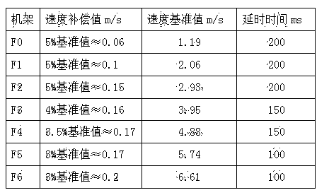
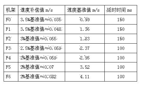
[0015] High-strength steel TQ750 specification 3mm * 1250mm and TQ700 specification 7mm * 1250mm two specifications of hot rolling finishing stand compensation speed drop control method, the speed compensation value of each stand is as follows:
[0016] 3mm*1250mm
[0017] .
[0018]
[0019] 7mm*1250mm
[0020]
Login to View More PUM
 Abstract
The invention relates to a control method of compensation speed decrease of a hot continuous rolling finish rolling rack, belonging to the field of steel rolling. According to the method, before steel is bitten by the finish rolling rack, a speed compensation value is applied to the rack in advance, and the speed compensation value is 2-5% of the rack speed reference value; after the steel is bitten for 100-200ms, the speed compensation value is canceled, and the rack speed reference value is recovered for rolling. After the method is adopted, the speed decrease of the rack which bites the steel can be reduced, a strip steel movable sleeve between racks is normally controlled, the rolled waste steel is reduced, and good benefit is obtained.
Description
technical field [0001] The invention belongs to the field of steel rolling, and in particular relates to an automatic speed control method of a hot continuous strip steel finishing rolling unit. Background technique [0002] Due to the different materials and temperatures of the special steel varieties rolled by Taiyuan Iron and Steel Co., Ltd., the rolling pressure and speed drop are large when the strip is threaded in the finishing rolling unit, which can easily cause abnormal movement of the looper between the stands, resulting in Unstable rolling of finish rolling may even produce scrap steel and damage mechanical equipment. Therefore, to solve the problem of different speed drops under different loads of finishing stands and to ensure rolling stability, one of the keys is the compensation speed drop control of hot rolling finishing stands. Contents of the invention [0003] The purpose of the present invention is to effectively ensure the action of the looper between...
Claims
Login to View More Application Information
Patent Timeline
 Patent Type & Authority Applications(China)
IPC IPC(8): B21B37/58
Inventor 张世厚康炜
Owner SHANXI TAIGANG STAINLESS STEEL CO LTD
Features
- Generate Ideas
- Intellectual Property
- Life Sciences
- Materials
- Tech Scout
- Unparalleled Data Quality
- Higher Quality Content
- 60% Fewer Hallucinations
Learn More Browse by: Latest US Patents, China's latest patents, Technical Efficacy Thesaurus, Application Domain, Technology Topic, Popular Technical Reports.
© 2025 PatSnap. All rights reserved.Legal|Privacy policy|Modern Slavery Act Transparency Statement|Sitemap|About US| Contact US: help@patsnap.com


