Movable shaft mechanism of belt test machine

A technology for testing machines and moving shafts, applied to measuring devices, applying stable tension/pressure to test material strength, instruments, etc., can solve problems such as easy loosening, slipping, and easy breaking

Inactive Publication Date: 2014-12-10
SUZHOU ISHIMARU ERI PML PRECISION MECHANISM CO LTD
View PDF4 Cites 0 Cited by
  • Summary
  • Abstract
  • Description
  • Claims
  • Application Information

AI Technical Summary

Problems solved by technology

In this way, different belts need to be tested differently. Ordinary belts use the friction after tension to drive and drive surface objects. This kind of belt has certain requirements for tension. If it is too small, it is easy to loosen and slip, and if it is too large Tension

Method used


Image

  • Movable shaft mechanism of belt test machine

Examples


Embodiment Construction

[0007] The preferred embodiments of the present invention will be described in detail below in conjunction with the accompanying drawings, so that the advantages and features of the invention can be more easily understood by those skilled in the art, so as to define the protection scope of the present invention more clearly.

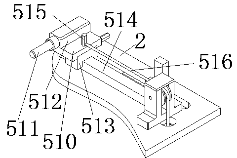
[0008] see figure 1 , the embodiment of the present invention includes:

[0009] A moving shaft mechanism of a belt testing machine, the moving shaft mechanism of the belt testing machine comprises a moving shaft slide table 510, a moving shaft 511 of a belt cover, a moving shaft seat 512, a slider 513 and a slide rail 514, the belt of the cover The moving shaft 511 is inserted into the moving shaft seat 512, and the moving shaft seat 512 is fixed on the moving shaft slide table 510, and the bottom of the moving shaft slide table 510 is provided with a slider 513, and the slide block 513 is installed on the slide rail 514, and the slide rail 514 is fixed...


PUM


Abstract

The invention discloses a movable shaft mechanism of a belt test machine. The movable shaft mechanism of the belt test machine comprises a movable shaft sliding table, a movable shaft for sleeving a belt, a movable shaft base, a slider and a sliding rail, wherein the movable shaft for sleeving the belt is inserted in the movable shaft base, the movable shaft base is fixed on the movable shaft sliding table, the slider is arranged at the bottom of the movable shaft sliding table and mounted on the sliding rail, the sliding rail is fixed on a test table top, and the movable shaft sliding table is connected with one end of a traction line through a hexagonal pin. Through the mode, the tolerance of the belt under maximum tension can be intuitively tested, and the stretching condition of the belt surface can be intuitively observed.

Description

technical field [0001] The invention relates to the field of automatic testing machinery, in particular to a moving shaft mechanism of a belt testing machine. Background technique [0002] The belt is one of the standard parts for transmission in automatic machinery, and it is widely used. At the same time, according to different usage occasions, the belt is divided into many different categories, and its performance requirements are also different. In this way, different belts need to be tested differently. Ordinary belts use the friction after tension to drive and drive surface objects. This kind of belt has certain requirements for tension. If it is too small, it will easily loosen and slip, if it is too large prone to breakage. Contents of the invention [0003] The technical problem mainly solved by the present invention is to provide a moving shaft mechanism of a belt testing machine, which can intuitively test the tolerance of the belt under the maximum tension and...

Claims


Application Information

Patent Timeline
Patent Type & Authority Applications(China)
IPC IPC(8): G01N3/02G01N3/08
Inventor 施建兰
Owner SUZHOU ISHIMARU ERI PML PRECISION MECHANISM CO LTD
Why Eureka
Try Eureka