


Quick Research
Generate reliable direction feasibility study reports for your R&D in just a few steps.

Technical Q&A
Discover and master advanced knowledge NOW. Basics, ideas, possibilities, all at once.

Find Solutions
As an expert in R&D theories, this can generate solutions to your technical problems instantly.

Evaluate Feasibility
Analyze your overall solution with one click, know your potential R&D risks in advance.

Monitor Landscape
Get weekly tech updates, stay abreast of the latest tech innovations and key insights.
Atomizer capable of being applied to mobile platform
A mobile platform, atomizer technology, applied in the field of atomizers, can solve problems such as unreliable application
- Summary
- Abstract
- Description
- Claims
- Application Information
AI Technical Summary
Problems solved by technology
Method used
Image

Examples
Embodiment 1
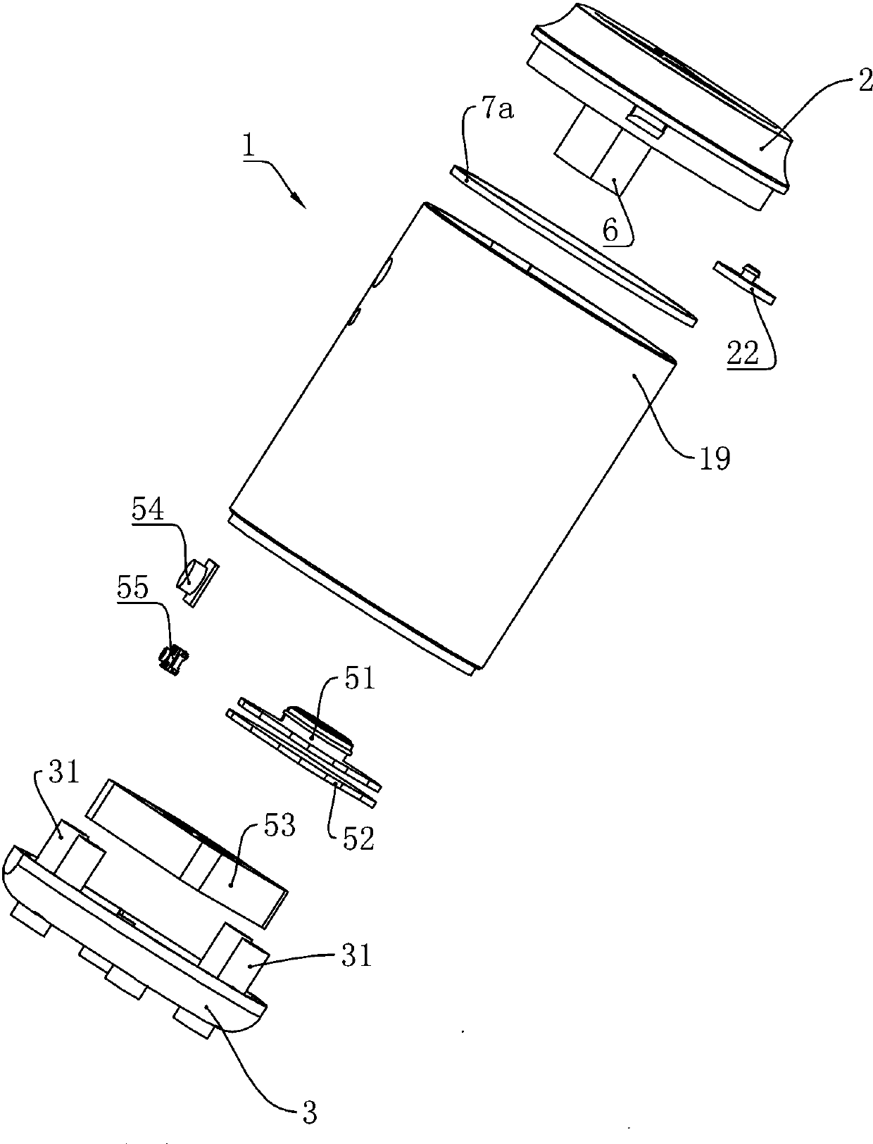
[0033] Embodiment one, such as figure 1 As shown, the atomizer 1 mainly includes a top cover 2 , a cavity 19 and a bottom cover 3 .
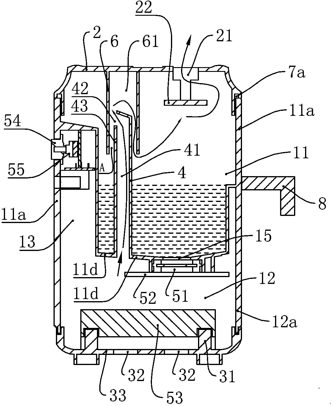
[0034] Such as figure 1 and figure 2 As shown, the cavity 19 includes an atomizing cavity 11 , a main appliance cavity 12 disposed below the atomizing cavity 11 , and an auxiliary appliance cavity 13 set on the side wall of the atomizing cavity 11 . Wherein, the atomizing chamber 11 includes a barrel-shaped side wall 11a, a top cover 2 and a bottom wall 11d, and the main appliance chamber 12 is composed of the bottom wall 11d, the side wall 12a and the bottom cover of the atomizing chamber 11. 3, the bottom wall 11d of the atomization chamber 11 isolates the atomization chamber 11 from the main appliance chamber 12. An air inlet 32 is also arranged on the chamber wall of the main electrical appliance chamber 12, that is, the bottom wall 33 of the bottom cover 3, and a fan 53, a control circuit 52 and an ultrasonic generator 51 are sequenti...
Embodiment 2
[0047] Embodiment 2 is different from Embodiment 1 in that, as Figure 5 As shown, the atomization chamber 11 can also adopt another embodiment, the top cover 2 and the side wall 11a of the atomization chamber 11 are integrally formed, the bottom wall 11d of the atomization chamber 11 and the side wall 11a are detachably connected. In order to prevent the liquid in the receiving chamber 11 from leaking out from the gap between the bottom wall 11d and the side wall 11a of the atomization chamber 11, between the bottom wall 11d and the side wall 11a of the atomization chamber 11 A sealing ring 7b is provided. This facilitates installation, maintenance and cleaning of the atomizing device 51 disposed on the bottom wall 11d of the atomizing chamber 11 .
Embodiment 3
[0048] The third embodiment is different from the first embodiment in that the liquid shield 6 also adopts another implementation, such as Figure 5 As shown, the upper end portion 43 of the air guide column 4 is provided with four support arms 44 arranged at intervals from each other. The liquid shield 6 is a component independent of the wind guiding column 4 but positioned on the support arm 44 of the wind guiding column 4 so as to be positioned on the wind guiding column 4 . In order to prevent the liquid shield 6 from loosening and detaching from the wind guide column 4, glue can be added between the liquid shield 6 and the support arm 44 to bond the liquid shield 6 on the on the support arm 44. At this time, the airflow delivered by the air outlet 42 passes through the gap between the gap A and the support arm 44 and then flows toward the atomizing chamber 11 . As for the button 55 and the signal light 56, they can be arranged on the side wall 12a of the main electrical...
PUM
 Abstract
Description
Claims
Application Information
 - R&D Engineer
- R&D Manager
- IP Professional
- Industry Leading Data Capabilities
- Powerful AI technology
- Patent DNA Extraction
Browse by: Latest US Patents, China's latest patents, Technical Efficacy Thesaurus, Application Domain, Technology Topic, Popular Technical Reports.
© 2024 PatSnap. All rights reserved.Legal|Privacy policy|Modern Slavery Act Transparency Statement|Sitemap|About US| Contact US: help@patsnap.com