LED lamp tube

A technology of LED lamps and LED light sources, applied in the field of LED lamps, can solve problems such as inaccessible maintenance, affecting luminous effect, complex structure, etc., and achieves the effects of simple and convenient maintenance, flexible installation and disassembly, and flexible installation and disassembly

Inactive Publication Date: 2014-12-10
陈美飞
View PDF0 Cites 0 Cited by
  • Summary
  • Abstract
  • Description
  • Claims
  • Application Information

AI Technical Summary

Problems solved by technology

The existing end cover structure is an integrated structure, which is directly fixed at both ends of the tube body, so that the entire LED tube becomes a sealed structure. Once the LED tube is assembled, it is impossible to open or observe the internal structure, and it is impossible to understand the inside Due to the situation, it is impossible to carry out later inspection and maintenance. Once there is a problem with the drive device and the circuit, it cannot be repaired, resulting in a shorter service life of the LED lamp.
[0003] Moreover, the existing driving device is generally glued to the inside of the end cover structure by glue. The positioning and fixing effect of the glue is weak. Into the body of the tube, affecting the normal use of the LED tube, affecting the luminous effect
[0004] Existing LED lamp tubes are generally installed on the mounting surface through mounting brackets, which requires additional production of brackets, complex structure, large volume, waste of materials, increased processing procedures, resulting in complicated and cumbersome production and processing, low production efficiency, and high production costs.

Method used


Image

  • LED lamp tube
  • LED lamp tube
  • LED lamp tube

Examples


Embodiment Construction

[0023] It should be understood that the specific embodiments described here are only used to explain the present invention, not to limit the present invention.

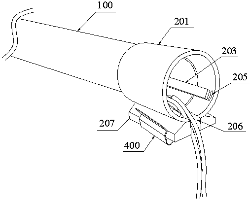
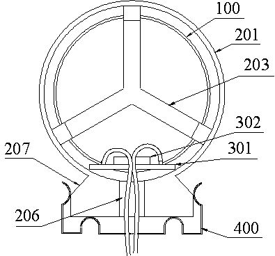
[0024] refer to Figure 1 to Figure 6 , an embodiment of an LED lamp tube of the present invention is proposed, including a tube body 100 , end cap structures disposed at both ends of the tube body 100 , and an LED light source assembly disposed in the tube body 100 .

[0025] The end cap structure includes an end cap tube 201 connected and fixed at both ends of the tube body 100 , and a cover body 202 that fits in shape with the end cap tube 201 and is engaged and fixed on the outer surface of the end cap tube 201 . The setting of the cover body 202 facilitates inspection and maintenance of the driving device 303 and the circuit.

[0026] The LED light source assembly includes a substrate 301 fixed inside the tube body 100 , an LED lamp bead 302 arranged on the substrate 301 , and a driving device 303 electrically c...


PUM


Abstract

The invention discloses an LED lamp tube which comprises a tube, end cover structures, LED light source assemblies and mounting hang plates. The LED lamp tube has the advantages that each end cover structure comprises an end cover barrel and a cover, clamp blocks and clamp grooves can be clamped with one another, so that the covers can be fixedly connected with the end cover barrels, the LED lamp tube is flexible in structure, and maintenance work can be carried out easily and conveniently; the LED light source assemblies comprise substrates, LED lamp beads and driving devices, the driving devices are arranged in the end cover barrels, a fixing frame is arranged at the end, which is close to the tube, of each end cover barrel and is used for limiting and fixing the corresponding driving device, and the driving devices can be fixed to positions between the end cover barrels and the covers by the aid of the fixing frames and can be prevented from slipping into the tube to affect normal use of the LED lamp tube; the lower ends of the end cover barrels extend out of clamp plates, the mounting hang plates can be mounted on a mounting surface, the upper ends of the mounting hang plates are inwardly bent to form elastic clips, the elastic clips are matched with the clamp plates and are fixedly clamped on the clamp plates, and accordingly the LED lamp tube is flexible in mounting and detaching; additional supports for the integral LED lamp tube are omitted, accordingly, materials can be saved, the LED lamp tube is convenient to manufacture and process, and the manufacturing cost can be effectively reduced.

Description

technical field [0001] The invention relates to the field of LED lamps, in particular to an LED lamp tube. Background technique [0002] LED light tubes are widely used in various places such as home and office lighting. LED light tubes generally include a tube body, end cap structures disposed at both ends of the tube body, and LED light source components disposed in the tube body. The existing end cover structure is an integrated structure, which is directly fixed at both ends of the tube body, so that the entire LED tube becomes a sealed structure. Once the LED tube is assembled, it is impossible to open or observe the internal structure, and it is impossible to understand the inside Due to the situation, it is impossible to carry out later inspection and maintenance, and once there is a problem with the drive device and the circuit, it cannot be repaired, resulting in a shorter service life of the LED lamp. [0003] Moreover, the existing driving device is generally glu...

Claims


Application Information

Patent Timeline
Patent Type & Authority Applications(China)
IPC IPC(8): F21V17/10F21V19/00F21Y101/02
Inventor 陈美飞
Owner 陈美飞
Why Eureka
Try Eureka