a wet clutch

A technology of wet clutches and clutch housings, applied in the field of clutches, which can solve problems such as the journal being easily damaged by tension, assembly difficulties, and changes in material properties, to achieve improved limit bearing capacity, simple structure and processing, and improved bearing capacity Effect

Active Publication Date: 2017-09-22
CHONGQING GEARBOX
View PDF7 Cites 0 Cited by
  • Summary
  • Abstract
  • Description
  • Claims
  • Application Information

AI Technical Summary

Problems solved by technology

[0003] In the existing wet clutch, the force of the working oil on the clutch friction plate is transmitted to the retaining ring, which is connected to the clutch housing, and the structure is complex, and the retaining ring needs to bear a large axial force. When the oil pressure fluctuates or When the friction plates of the clutch are combined and separated, the retaining ring has to bear a large impact force, which requires high load-bearing reliability of the retaining ring. If the thickness of the retaining ring is increased to improve the load-bearing reliability, not only the axial length of the clutch will be increased, but at the same time It will also make it difficult to assemble
In addition, the clutch will generate a lot of heat when the friction plate is running. If the generated heat cannot be taken away by the lubricating oil in time, it will cause the clutch to heat up. The existing solution is to drill holes in the clutch housing and pass through the These holes throw the lubricating oil from the inside of the clutch and take away the heat. However, when the clutch is running at high speed, the heat dissipation effect of this method is not ideal, and it is easy to cause the lubricating oil to not be discharged from the clutch in time, causing the clutch to heat up seriously.
In addition, the assembly between the transmission shaft of the existing clutch and the oil cylinder or gear adopts the method of shrink fit. Although the assembly is convenient, it is troublesome to disassemble and replace after the gear or oil seal is damaged. Directly heating the oil cylinder or gear will easily change the material properties. Journals are more susceptible to tensile damage during disassembly
[0004] To sum up, how to solve the problem that when the friction plate is limited by the retaining ring, the bearing reliability of the retaining ring is not high, and increasing the reliability by increasing the thickness of the retaining ring will lead to an increase in the axial length of the clutch has become an urgent need for those skilled in the art. solved problem

Method used


Image

  • a wet clutch
  • a wet clutch
  • a wet clutch

Examples


Embodiment Construction

[0028] The core of the present invention is to provide a wet clutch, which improves the limited bearing capacity of the friction plates without increasing the axial length of the clutch.

[0029] The following will clearly and completely describe the technical solutions in the embodiments of the present invention with reference to the accompanying drawings in the embodiments of the present invention. Obviously, the described embodiments are only some, not all, embodiments of the present invention. Based on the embodiments of the present invention, all other embodiments obtained by persons of ordinary skill in the art without making creative efforts belong to the protection scope of the present invention.

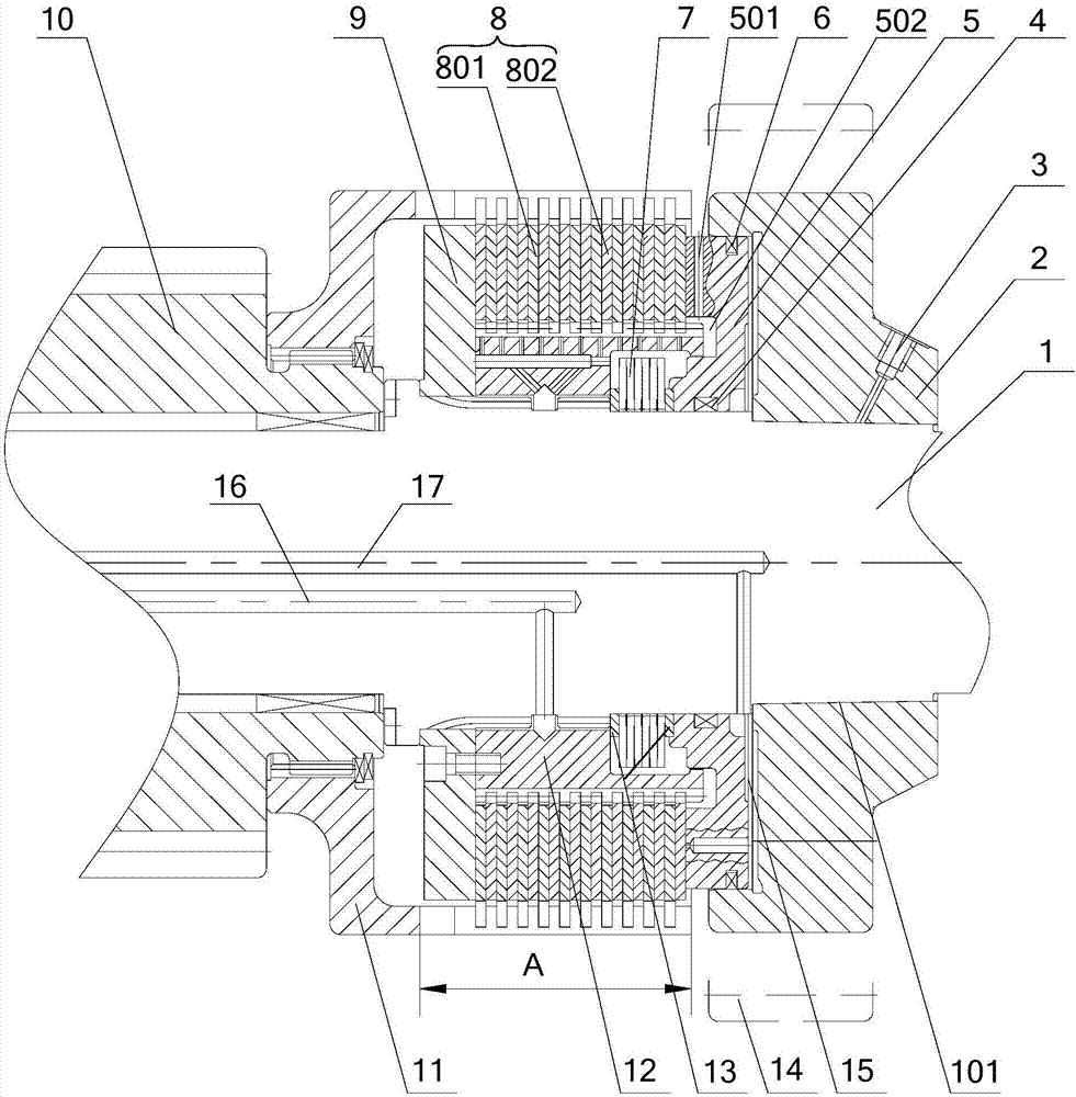
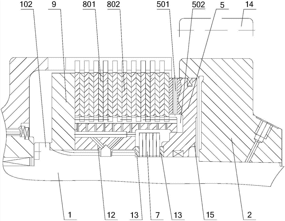
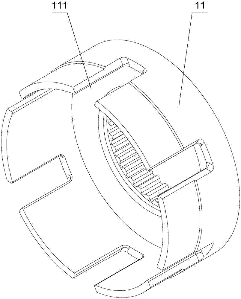
[0030] Please refer to Figure 1-Figure 3 , figure 1 A schematic structural diagram of a wet clutch provided by an embodiment of the present invention; figure 2 for figure 1 Partial enlarged view in ; image 3 It is a structural schematic diagram of a clutch housing of ...


PUM


Abstract

The application discloses a wet clutch, comprising a transmission shaft, a friction plate seat, a clutch housing, a friction plate group and a piston, the friction plate seat is circumferentially fixed on the transmission shaft, the piston is slidably sleeved on the transmission shaft, and the internal friction The friction plate and the outer friction plate form a friction plate group; it also includes a friction plate baffle fixed at one end of the friction plate seat; the friction plate baffle is in limit contact with one side of the friction plate group, and the piston is limited with the other side of the friction plate group. Contact; a limit step is set on the transmission shaft to limit contact with the friction plate baffle. In this wet clutch, the friction plate baffle restricts the axial movement of the friction plate group along the transmission shaft, and the friction plate baffle is in contact with the limit step, which will eventually reduce the axial force acting on the friction plate group and the pressure caused by the separation and combination of the clutch. The generated impact force is transmitted to the transmission shaft, and the axial bearing capacity of the transmission shaft is much larger than that of the retaining ring. Therefore, the limit bearing capacity of the friction plate is improved without increasing the axial length of the clutch.

Description

technical field [0001] The invention relates to the technical field of clutches, in particular to a wet clutch. Background technique [0002] The wet clutch presses multiple steel plates and friction plates through the action of the hydraulic cylinder to combine the clutch. After oil is unloaded, the steel plates and friction plates are separated under the action of the spring force. Through separation and combination, it is determined whether the power shaft of the next stage is transmitted. The power of the previous shaft. [0003] In the existing wet clutch, the force of the working oil on the clutch friction plate is transmitted to the retaining ring, which is connected to the clutch housing, and the structure is complex, and the retaining ring needs to bear a large axial force. When the oil pressure fluctuates or When the friction plates of the clutch are combined and separated, the retaining ring has to bear a large impact force, which requires high load-bearing relia...

Claims


Application Information

Patent Timeline
Patent Type & Authority Patents(China)
IPC IPC(8): F16D25/0638
Inventor 游勇余业亮吕和生
Owner CHONGQING GEARBOX
Why Eureka
Try Eureka