Heating device for textiles
A technology for heating devices and textiles, applied in the field of textiles, can solve the problems of improper use of heating wires, easy to catch fire, electromagnetic radiation harmful to human body, endangering life safety, etc., to achieve the effects of fast and stable heating, easy operation, and prevention of leakage
- Summary
- Abstract
- Description
- Claims
- Application Information
AI Technical Summary
Problems solved by technology
Method used
Image
Examples
Embodiment 1
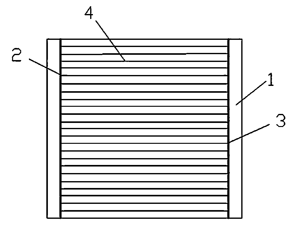
[0031] Such as figure 2 Shown is the first embodiment of the heat generating body layer of the present invention. The heat generating body layer 10 includes a textile fabric 1, a first main wire 2, a second main wire 3 and a first main wire 3 arranged in parallel on the textile fabric 1. A plurality of carbon fibers 4 are arranged in parallel between the main conductor 2 and the second main conductor 3. The two ends of the carbon fiber 4 are electrically connected to the first main conductor 2 and the second main conductor 3 respectively. The first main conductor 2 and the second main conductor The main conductor 3 is connected to the power cord, and the parallel connection of the carbon fiber and the main conductor makes it possible to maintain the normal working condition of the heating main layer when a single or multiple carbon fibers are broken, which greatly extends the product Service life; at the same time, the carbon fibers in the heating main layer are densely arrange...
Embodiment 2
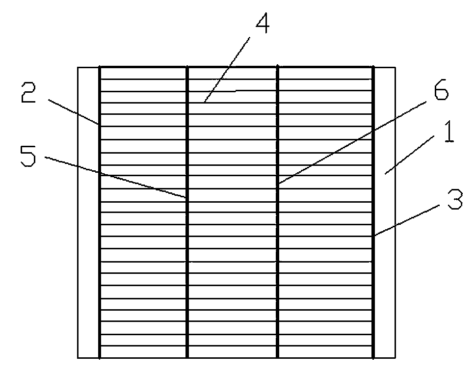
[0033] Such as image 3 Shown is the second embodiment of the heat-generating body layer of the present invention. The difference from the first embodiment is that: between the first main wire 2 and the second main wire 3, a second main wire parallel to the first main wire 2 is also provided. The three main wires 5 and the fourth main wire 6 have the same distance between adjacent main wires. The third main wire 5 and the fourth main wire 6 are electrically connected to the carbon fiber vertically, and the first main wire 2 and the fourth main wire The line 6 is connected to the same power line, and the third main line 5 and the second main line 3 are connected to the same power line. This structure is generally applied to products with a large heating body layer width, which ensures that when the heating body layer is very wide, the heating efficiency is improved. When a carbon fiber between the first main conductor and the third conductor is broken and damaged Later, the part...
Embodiment 3
[0035] Figure 4 It is the third embodiment of the heat generating body layer of the present invention. The difference from the first embodiment is that: a fifth main conductor parallel to the first main conductor 2 is also provided between the first main conductor 2 and the second main conductor 3 Line 7, the distance between adjacent main lines is the same, the fifth main line 7 is electrically connected to the carbon fiber vertically, the first main line 2 and the second main line 3 are connected to the same power line, and the fifth main line 7 is connected to one A power cord. This improves the heating efficiency of the heating main body layer to a certain extent. When any one of the carbon fibers between the first main wire 2 and the fifth main wire 7 is broken, it will not affect the fifth main wire 7 and the second main wire 3 Any carbon fiber in between works normally, thus ensuring that the carbon fiber breaks as little as possible to affect the heating effect.
[0036...
PUM
| Property | Measurement | Unit |
|---|---|---|
| Length | aaaaa | aaaaa |
| Width | aaaaa | aaaaa |
| Width | aaaaa | aaaaa |
Abstract
Description
Claims
Application Information
 - R&D Engineer
- R&D Manager
- IP Professional
- Industry Leading Data Capabilities
- Powerful AI technology
- Patent DNA Extraction
Browse by: Latest US Patents, China's latest patents, Technical Efficacy Thesaurus, Application Domain, Technology Topic, Popular Technical Reports.
© 2024 PatSnap. All rights reserved.Legal|Privacy policy|Modern Slavery Act Transparency Statement|Sitemap|About US| Contact US: help@patsnap.com


