Disassembly and assembly system and disassembly method of vibrating ore drawer motor

A mining machine, square technology, applied in the direction of metal processing, metal processing equipment, manufacturing tools, etc., can solve the problems of dangerous working environment and working state, limited space for disassembling and assembling the motor, and heavy weight of the motor, so as to eliminate potential safety hazards , increase safety and reliability, and save space

Active Publication Date: 2016-05-04
鞍钢集团矿业设计研究院有限公司
View PDF7 Cites 0 Cited by
  • Summary
  • Abstract
  • Description
  • Claims
  • Application Information

AI Technical Summary

Problems solved by technology

[0003] The vibrating motor is installed at the bottom of the vibrating ore-drawing machine. Usually, the height of the motor from the standing platform is 1.78m, and the height of the standing platform from the ground is 2.48m. When removing or installing the motor, it is difficult to cross these two heights, especially the The height from the standing platform to the bottom of the vibrating mining machine is the most difficult. The traditional method of disassembling and assembling the motor is to lift or lower the motor manually by manually lifting the pulley, but the weight of the motor is relatively heavy (350kg). The space is limited (the width direction is only 800mm, while the motor size is usually 720×500mm, and the distance between the two ends of the motor and the wall is only 47mm), there is almost no work space for people after installing the manual lifting pulley, and it is necessary to accurately align the bolts Therefore, it is very difficult to disassemble and assemble the motor of the vibrating ore-drawing machine at present, the labor intensity is high, the work efficiency is low, the working environment and working state are very dangerous, and there are great potential safety hazards

Method used


Image

  • Disassembly and assembly system and disassembly method of vibrating ore drawer motor
  • Disassembly and assembly system and disassembly method of vibrating ore drawer motor
  • Disassembly and assembly system and disassembly method of vibrating ore drawer motor

Examples


Embodiment Construction

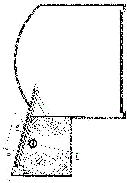
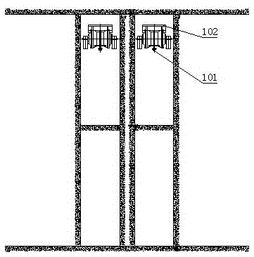
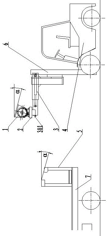
[0041] Such as Figure 1-a to Figure 4 As shown, the vibrating ore drawing machine motor disassembly system is composed of a self-propelled disassembly vehicle 4 assembled with a telescopic arm 3 and a motor clamping device 2, and a motor loading frame 5 for being arranged on a carrier vehicle 7.

[0042]Wherein, a vertical mast 6 is installed in front of the chassis of the self-propelled dismantling vehicle 4, the support of the telescopic arm 3 is installed on the vertical mast 6, and the vertical mast 6 is additionally provided with The lifting cylinder that drives the telescopic arm 3 to reciprocate up and down (omitted in the figure, a lifting cylinder structure integrated with the vertical mast can be used, which is commercially available), and the motor clamping device 2 is sent to the motor 1 The height where the oil inlet and outlet of the hydraulic cylinder in the telescopic arm 3 is connected with the hydraulic valve group arranged at the lower part of the cab of th...


PUM


Abstract

The invention relates to a vibrating ore drawing machine motor disassembly system and disassembly method, which is characterized in that: it is composed of a self-propelled disassembly vehicle assembled with a telescopic arm and a motor clamping device and a motor loading frame, the self-propelled disassembly vehicle A vertical mast is installed in front of the chassis. The support of the telescopic arm is installed on the vertical mast and is moved up and down by the lifting cylinder. The motor clamping device is set at the front end of the telescopic arm. Composed of fastening parts and positioning pins, the upper surface of the sliding bracket is provided with a supporting body corresponding to the outer peripheral surface of the motor of the vibrating ore drawing machine, and a nylon liner is provided between the lower surface of the sliding bracket and the inner surface of the base, and the locking part is provided by the corresponding vibration The hoisting ring of the ore-drawing machine motor and the lock nuts and bolts clamped therein are composed. The motor loading frame is composed of support frames on both sides, a connecting frame connected to one end of the support frames on both sides, and a support plate fixed on the top of the support frames on both sides. group composition. It replaces the manual operation, the operation is safe and fast, the labor intensity is reduced, and the work efficiency is improved.

Description

technical field [0001] The invention relates to a technology for disassembling and assembling a vibrating ore-drawing machine motor located at a high place, in particular to a vibrating ore-drawing machine motor disassembling system and a disassembling method thereof. Background technique [0002] Vibrating ore-drawing machine is one of the main equipments for underground production. It undertakes the task of ore-drawing and loading in the underground, which is the key link to complete the underground transportation. Generally, the power of each vibrating ore-drawing machine comes from two vibration motors (such as ZDJ10-6 type), and the vibration generated by the vibration motor meets the working requirements of ore-drawing and loading. Due to the harsh working environment and high impact load, the vibration motor often breaks down and needs to be disassembled and replaced in time. At the same time, the tense underground production and transportation tasks require the repla...

Claims


Application Information

Patent Timeline
Patent Type & Authority Patents(China)
IPC IPC(8): B23P19/04
CPCB23P19/04
Inventor 王明华高志敏张利刚史长胜李兴王雷
Owner 鞍钢集团矿业设计研究院有限公司
Why Eureka
Try Eureka