
A phase shifting unit

A technology of phase shifting and dielectric board, which is applied in the direction of electrical components, circuits, waveguide devices, etc., and can solve the problems of large line loss and heavy weight

Active Publication Date: 2017-05-10
COMBA TELECOM TECH (GUANGZHOU) CO LTD
View PDF19 Cites 0 Cited by
  • Summary
  • Abstract
  • Description
  • Claims
  • Application Information

AI Technical Summary

Problems solved by technology

However, if the conductor sliding type phase shifter adopts a cavity structure, the weight is relatively heavy; if a microstrip line structure without a closed cavity is adopted, there will be a problem that the line loss caused by parasitic radiation and coupling loss is too large

Method used


Image

  • A phase shifting unit
  • A phase shifting unit
  • A phase shifting unit

Examples


Embodiment Construction

[0030] The present invention will be described in detail below in conjunction with the accompanying drawings and embodiments.

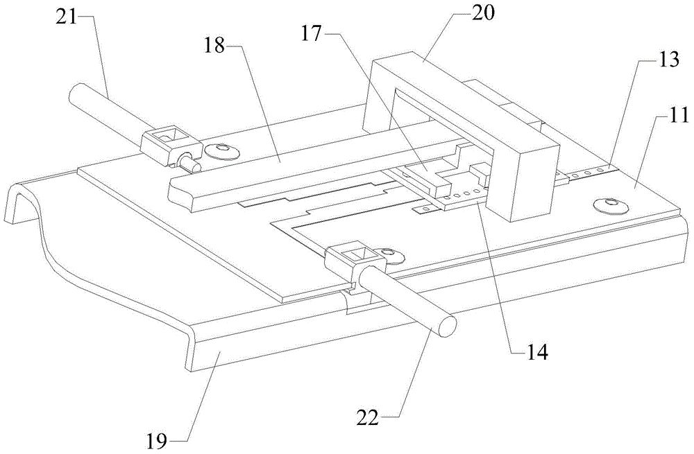
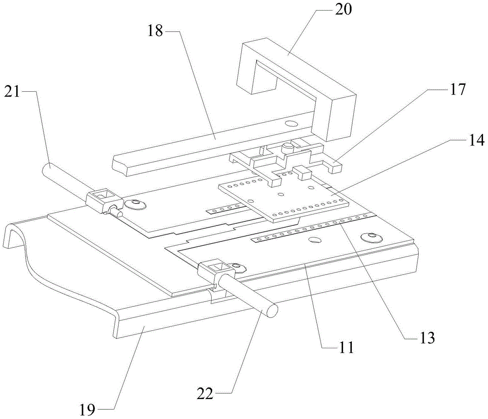
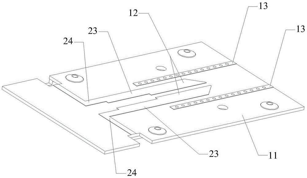
[0031] see figure 1 , figure 2 , image 3 , Figure 4 and Figure 5 , figure 1 is a schematic structural diagram of an embodiment of the phase shifting unit of the present invention, figure 2 yes figure 1 An exploded view of the phase-shifting unit shown, Figure 3-5 yes figure 1 The schematic diagram of the local structure of the phase-shifting unit shown, such as Figure 1-5 As shown, the phase shifting unit includes: a first dielectric plate 11, a parallel conductor strip 12, a first metal ground (not shown), a first ground strip 13, a second dielectric plate 14, a U-shaped conductor strip 15, a second metal ground A ground (not shown in the figure), a second ground strap 16 , a connecting piece 17 , a pull rod 18 , a mounting plate 19 , a pressing piece 20 , an input port 21 and an output port 22 .

[0032] Wherein, the phase shifting ...


PUM


Abstract

The invention discloses a phase shift unit. The phase shift unit comprises a first medium plate and a second medium plate. The two surfaces of the first medium plate are respectively provided with parallel conductor strips and first metal ground, and the two sides of each parallel conductor strip are each provided with a first grounding strip along a longitudinal direction; the two surfaces of the second medium plate are respectively provided with a U-shaped conductor strip and second metal ground, and the two sides of the U-shaped conductor strip are each provided with a second grounding strip along the direction of two parallel arms; the first medium plate and the second medium plate are arranged to the opposite to each other, the parallel conductor strips are in one-to-one correspondence with the two parallel arms of the U-shaped conductor strip for realizing electrical coupling, and each first grounding strip and each second grounding strip are in one-to-one correspondence for realizing electrical coupling; and the U-shaped conductor strip can move along the longitudinal direction of the parallel conductor strips so as to realize phase shift of signals. Such a structure enables the phase shift unit to have the advantages of light weight and small line and to realize high-efficiency transmission of the signals at the time when the phase shift is realized.

Description

technical field [0001] The invention relates to the field of radio frequency devices, in particular to a phase shifting unit. Background technique [0002] In the mobile communication base station antenna, the phase shifter is the core component of the antenna, and its realization generally has two types: dielectric sliding type and conductor sliding type. [0003] The medium sliding phase shifter often needs a metal cavity for accommodating the sliding medium, and the medium sliding ΔL 1 The resulting phase change is: Among them, ε r1 is the relative permittivity of the coaxial medium, λ 0 is the free space wavelength, ΔL 1 is the sliding stroke. [0004] Some conductor sliding phase shifters use a closed cavity to make the conductor a stripline; some do not use a closed cavity to make the conductor a microstrip line. Conductor sliding ΔL 2 The resulting phase change is: Among them, ε r2 is the relative permittivity of the microstrip dielectric substrate, λ 0 is...

Claims


Application Information

Patent Timeline
Patent Type & Authority Patents(China)
IPC IPC(8): H01P1/18
Inventor 赖展军卢吉水张晓
Owner COMBA TELECOM TECH (GUANGZHOU) CO LTD
Learn More