
A driving device, an array substrate and a display device

A driving device and array substrate technology, which is applied in the field of array substrates, display devices, and driving devices, and can solve problems such as large test limitations, gate signal detection, and limited step space of liquid crystal display panels.

Active Publication Date: 2017-08-15
SHANGHAI TIANMA MICRO ELECTRONICS CO LTD +1
View PDF5 Cites 0 Cited by
  • Summary
  • Abstract
  • Description
  • Claims
  • Application Information

AI Technical Summary

Problems solved by technology

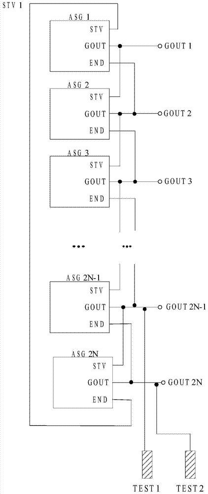
If the gate signal of the gate shift register ASG of the last stage or the second-to-last stage is tested to be abnormal, then each stage of the gate shift register ASG before that may work abnormally, but the The step space is limited, and the gate signal output by each gate shift register ASG cannot be pulled to the steps of the liquid crystal display panel, and the test has great limitations.
At the same time, after multiple gate shift registers ASG are cascaded together, when a certain stage of gate shift register ASG is slightly damaged, the output gate signal is distorted but the next stage of gate shift register can still be ASG is triggered, and all gate shift registers ASG after this stage of gate shift register ASG work normally. At this time, the output of the gate signal of the last or penultimate stage of gate shift register ASG is also normal. Yes, in this case, the abnormal operation of the gate shift register ASG of a certain stage cannot be detected by testing the gate signals of the gate shift register ASG of the last two stages

Method used


Image

  • A driving device, an array substrate and a display device
  • A driving device, an array substrate and a display device
  • A driving device, an array substrate and a display device

Examples


Embodiment Construction

[0018] The following will clearly and completely describe the technical solutions in the embodiments of the present invention with reference to the accompanying drawings in the embodiments of the present invention. Obviously, the described embodiments are only some, not all, embodiments of the present invention. Based on the embodiments of the present invention, all other embodiments obtained by persons of ordinary skill in the art without creative efforts fall within the protection scope of the present invention.

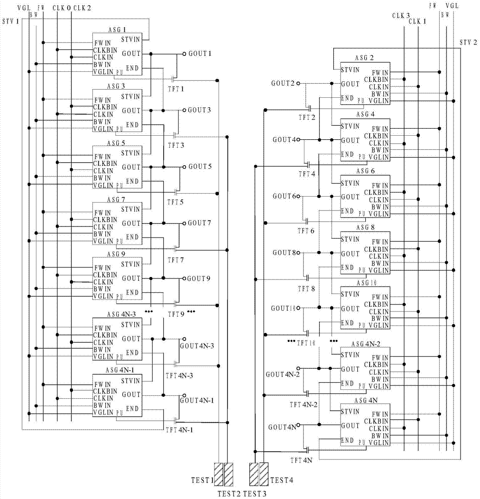
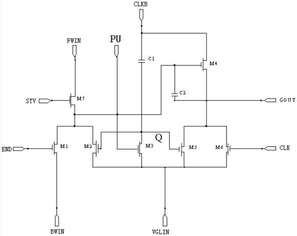
[0019] figure 2 It is a structural schematic diagram of a driving device provided by an embodiment of the present invention. Such as figure 2 As shown, the driving device includes a plurality of cascaded shift registers ASG. When driven by 9 signal lines, the signals transmitted on the 9 signal lines are: forward scanning signal FW, reverse scanning signal BW, the first An initial trigger signal STV1, a second initial trigger signal STV2, a 0th clock signal CLK...


PUM


Abstract

The invention discloses a driving device which comprises multiple cascaded shifting registers, multiple detection switches and multiple detection ends. The control ends of the detection switches are electrically connected with the shifting registers respectively. The first poles of the detection switches are electrically connected with the signal output ends of the shifting registers respectively. The second poles of the detection switches at least spaced by a level are electrically connected and jointly connected to the same detection end. Each detection end sequentially receives data signals of the shifting registers. Due to the fact that each detection end sequentially receives data signals of the shifting registers, the position of the abnormal shifting register can be directly, rapidly and accurately acquired, and an effective solution is provided for analysis of abnormality of a liquid crystal display panel.

Description

technical field [0001] The present invention relates to the field of display technology, in particular to a driving device, an array substrate and a display device. Background technique [0002] Liquid crystal displays (liquid crystal displays, LCDs) or organic light-emitting diodes (Organic Light-Emitting Diodes, OLEDs) have the advantages of low radiation, small size, and low energy consumption, and have gradually replaced traditional cathode ray tube displays (Cathode ray tubes) in some applications. Ray Tube display, CRT), and thus are widely used in information products such as notebook computers, personal digital assistants (Personal Digital Assistant, PDA), flat-screen TVs, or mobile phones. The traditional method of liquid crystal display is to use an external driver chip to drive the chips on the panel to display images, but in order to reduce the number of components and reduce manufacturing costs, it has gradually developed in recent years to make the driver circu...

Claims


Application Information

Patent Timeline
Patent Type & Authority Patents(China)
IPC IPC(8): G09G3/36G11C19/28
Inventor 李军王桂才周井雄张露
Owner SHANGHAI TIANMA MICRO ELECTRONICS CO LTD
Learn More