
Rear luggage rack device for sedan

A technology for luggage racks and cars, which is applied to vehicle parts, transportation and packaging, and can solve the problems of small ribs, insufficient rigidity of the rear bulkhead and local structural modes, and ineffective improvement of the rigidity of the rear bulkhead body.

Inactive Publication Date: 2014-12-03
PEUGEOT CITROEN CHINA AUTOMOTIVE TRADE +1
View PDF9 Cites 7 Cited by
  • Summary
  • Abstract
  • Description
  • Claims
  • Application Information

AI Technical Summary

Problems solved by technology

Therefore, for the rear luggage rack arrangement of the existing car, the noise will quickly enter the passenger compartment along the seat belt
[0003] In addition, in the existing cars, such as Figure 8 Smaller ribs are provided in the rear bulkhead body of the rear luggage rack assembly as shown, or as Figure 9 As shown, since the rear bulkhead body is provided with openings at positions corresponding to the openings of the rear bulkhead beam at the front, the length of the ribs provided along the longitudinal direction of the vehicle is relatively short, and the rigidity of the rear bulkhead body is relatively short. The improvement effect is not obvious
In this way, the rigidity and structural local modes of the rear bulkhead of the existing rear luggage rack device are insufficient

Method used


Image

  • Rear luggage rack device for sedan
  • Rear luggage rack device for sedan
  • Rear luggage rack device for sedan

Examples


Embodiment Construction

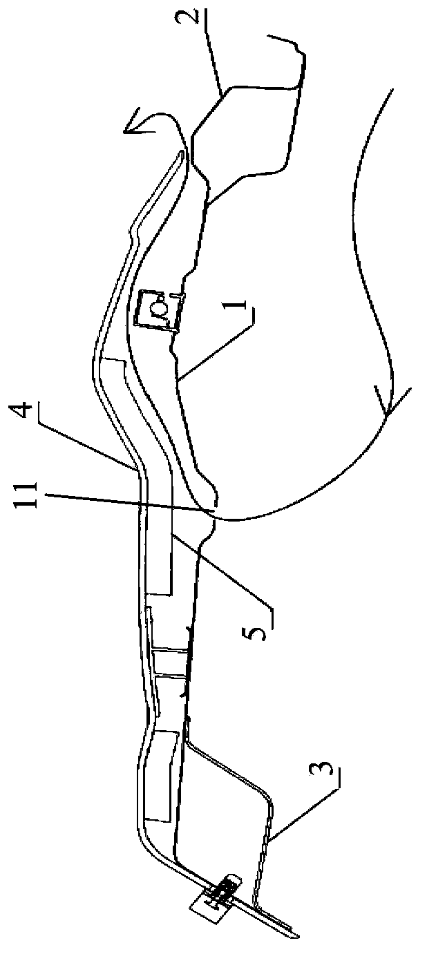
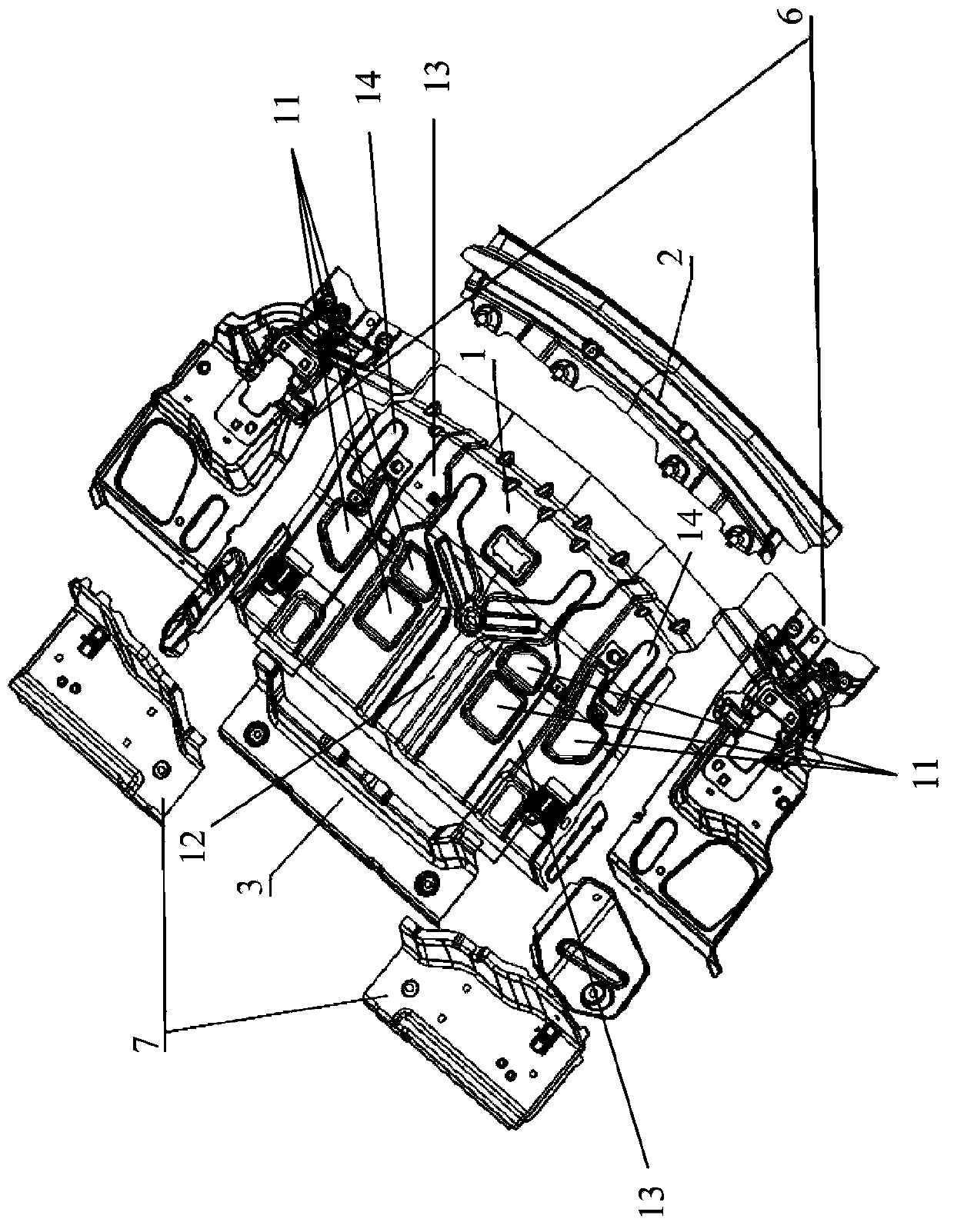
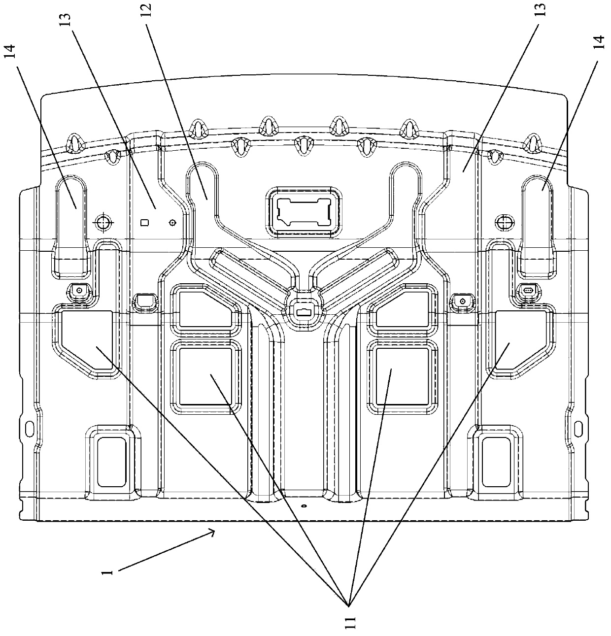
[0018] Such as figure 1 and figure 2 As shown, the rear luggage rack device of a car according to an embodiment of the present invention includes a rear bulkhead body 1 , a rear windshield lower beam 2 installed above the rear portion of the rear bulkhead body 1 , a rear bulkhead body 1 mounted on Rear bulkhead beam 3 under the front part, rear bulkhead trim 4 installed above the rear bulkhead body 1, rear bulkhead sound insulation foam installed between the rear bulkhead body 1 and rear bulkhead trim 4 5. The left and right rear bulkhead assemblies 6 installed on the lateral sides of the rear bulkhead body 1, and the left and right extension plates 7 of the rear bulkhead beam.

[0019] The rear bulkhead cross member 3 according to the invention itself has no opening towards the rear luggage compartment, so that the rear bulkhead cross member 3 is closed relative to the rear luggage compartment. In addition if figure 1 and 2 As shown, a plurality of through holes 11 ope...


PUM


Abstract

The invention discloses a rear luggage rack device for a sedan. A plurality of through holes which are towards an opening of a rear luggage compartment are formed at positions, which are behind a rear separator beam, on a rear separator body of the rear luggage rack device along the longitudinal direction of a vehicle; the rear separator beam is closed relative to the rear luggage compartment of the sedan; the rear separator body also comprises a Y-shaped reinforcing rib extending at the middle position on the rear separator body from the front end part of the rear separator body to the rear end part of the rear separator body and straight-line-shaped reinforcing ribs which are positioned at both sides of the Y-shaped reinforcing ribs, are separated from the Y-shaped reinforcing ribs and extend from the front end part of the rear separator body to the rear end part of the rear separator body.

Description

technical field [0001] The invention relates to a rear luggage rack device for a car, in particular to a rear luggage rack device for a sedan. Background technique [0002] In existing cars, a rear luggage rack device is provided between the rear seats and the rear windshield, such as Figure 6 and 7 As shown, in the rear luggage rack device, the road noise generated during driving passes through the pressure relief valve along the Figure 6 and 7 The path indicated by the arrow enters the trunk, after which the noise splits into two parts, as Figure 7 As shown, part of the noise as Figure 7 The path indicated by the arrow I passes through the opening of the rear bulkhead beam at the front, passes through the corresponding opening of the rear bulkhead body and passes along the gap between the rear bulkhead sheet metal and the sound insulation foam towards the rear of the car, and then Passed through the gap between the rear bulkhead trim and the rear windshield to the p...

Claims


Application Information

Patent Timeline
Patent Type & Authority Applications(China)
IPC IPC(8): B60R5/04
Inventor 汪振华高思健王世伟李天奇
Owner PEUGEOT CITROEN CHINA AUTOMOTIVE TRADE
Learn More