
Device and method for automatically welding box beam

An automatic welding and box beam technology, applied in the field of machinery, to achieve the effect of ensuring accuracy, simple structure and good rigidity

Active Publication Date: 2014-12-03
SHANDONG FENGHUI EQUIP TECH
View PDF8 Cites 7 Cited by
  • Summary
  • Abstract
  • Description
  • Claims
  • Application Information

AI Technical Summary

Problems solved by technology

[0003] The technical problem to be solved by the present invention is how to make the welding torch perform welding along the track of the camber in the automatic welding process of the web and the flange plate of the main girder with camber in the box girder welding process of the prior art The problem is to provide an automatic welding device and method for box girders, which can realize automatic welding of box girders of various sizes and cambers, so as to improve work efficiency and reduce labor intensity of workers

Method used


Image

  • Device and method for automatically welding box beam
  • Device and method for automatically welding box beam
  • Device and method for automatically welding box beam

Examples


Embodiment Construction

[0024] The present invention will be specifically described below in conjunction with the accompanying drawings and embodiments.

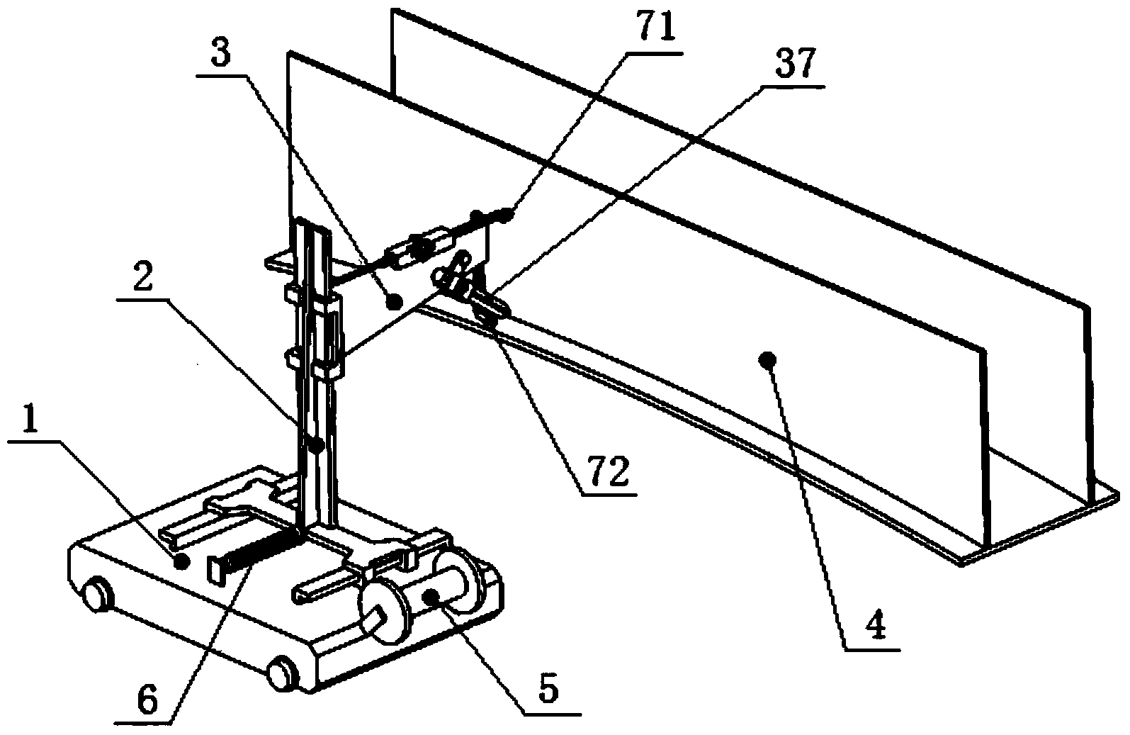
[0025] figure 1 Shown is the structural representation of the present invention.

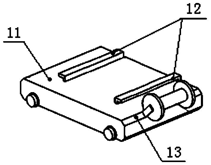
[0026] The present invention comprises a walking trolley 1, a main support 2, a welding torch support arm 3 and a welding torch 37, the welding torch 37 is arranged on the welding torch support arm 3 through a hinge shaft, and the welding torch support arm 3 is arranged on the vertical rectangular guide rail of the main support 2 through a slider 31 22, the walking trolley 1 is provided with a horizontal rectangular guide rail 12, the main support 2 cooperates with the horizontal rectangular guide rail 12 of the walking trolley 1 through the rectangular guide rail groove below, and the welding torch 37 can follow the welding torch support arm 3 along the horizontal rectangular guide rail 12 and vertically. The rectangular guide rail 22 moves horizontally or vertical...


PUM


Abstract

The invention discloses a device and method for automatically welding a box beam. The device comprises a walking trolley, a main support, a welding gun supporting arm and a welding gun. The welding gun is arranged on the welding gun supporting arm through a hinge shaft, and the welding gun supporting arm is arranged on a vertical rectangular guide rail of the main support. The main support is matched with a horizontal rectangular guide rail of the walking trolley through a rectangular guide rail groove below the main support, and the welding gun can move along the horizontal rectangular guide rail and the vertical rectangular guide rail. In the welding process, the height and the angle of the welding gun are well adjusted according to the camber of the box beam and the positions of a flange plate and a box beam web, and therefore automatic welding can be achieved. According to the device and method for automatically welding the box beam, the structure is simple, adjustment is easy, box beams of various sizes can be conveniently and automatically welded, the labor intensity of welding personnel is lowered, rigidity is high, the bearing capability is high, machining and maintaining are easy, and cost is saved. The box type beam is automatically welded, besides, H-shaped steel used in a steel structure workshop can be automatically welded, and the accuracy of a profiling outline can be effectively ensured.

Description

technical field [0001] The invention relates to a welding device and method, in particular to an automatic box beam welding device and method, belonging to the field of mechanical technology. Background technique [0002] The box girder structure is widely used in the field of hoisting machinery due to its simple manufacturing process and strong bearing capacity, and its characteristics are more obvious in the field of bridge cranes and portal cranes. In the manufacturing process of bridge cranes and portal cranes, the assembly and welding of main girders, end girders, and outriggers takes a long time. Most of these structures are box girders, so simplifying the manufacturing process of box girders can be used to reduce product costs. a breakthrough point. In the traditional box girder assembly welding process, the weld at the intersection of the web and the flange plate is a long straight line weld, which is completely possible to realize automatic welding. The size of th...

Claims


Application Information

Patent Timeline
Patent Type & Authority Applications(China)
IPC IPC(8): B23K37/02
CPCB23K37/0229B23K37/0247B23K37/0252B23K37/0294
Inventor 谭恺任梦鸿翟杰张通友
Owner SHANDONG FENGHUI EQUIP TECH
Learn More