Cold heading machine
A technology of cold heading machine and machine body, which is applied in the directions of heading and forging presses, swage forging presses, driving devices of forging presses, etc. It can solve the problems of unsuitable high-speed operation and heavy process, so as to simplify the heading process and improve production Efficiency and responsiveness
Active Publication Date: 2014-12-03
HUANGSHAN SHENGRUI HEAVY IND MACHINERY
View PDF7 Cites 29 Cited by
- Summary
- Abstract
- Description
- Claims
- Application Information
AI Technical Summary
Problems solved by technology
The S plate pushes out the cutting material, and then returns to its position with the help of a spring. The whole process is relatively cumbersome and not suitable for high-speed operation.
Method used
View moreImage
Smart ImageViewing Examples
Examples
Embodiment Construction
Login to View More PUM
 Abstract
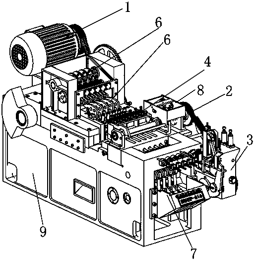
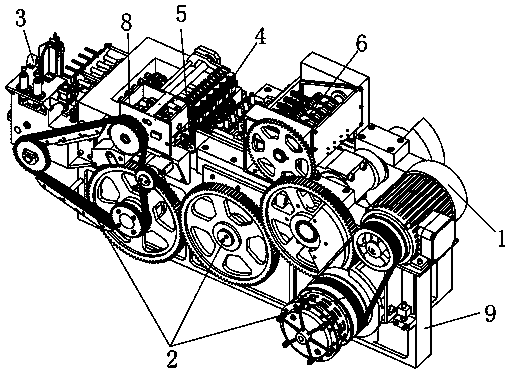
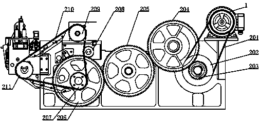
The invention discloses a cold heading machine. The cold heading machine comprises a machine body, wherein a main motor, a drive system, a linear feeding device, a rotary clamp, a cutter system, an adjustable male die ejecting mechanism and a closed back support are arranged on the machine body; the main motor is arranged at a first end of the machine body, and the drive system is arranged at an output end of the main motor; the linear feeding device is arranged at a second end of the machine body, and the closed back support is arranged on one side of the feeding device; the rotary clamp and the male die ejecting mechanism are arranged in the middle of the machine body; and the cutter system is arranged below the rotary clamp. After the main motor of the machine is started, the main motor drives the linear feeding device, the rotary clamp, cutters, the male die ejecting mechanism and the like through the drive system to finish processing steps of feeding, cutting, upsetting, finished product ejecting and the like. The cold heading machine has the advantages that the drive efficiency can be improved, the high-speed driving is realized, the working efficiency and precision of the cold heading machine are improved, and the like.
Description
technical field The invention relates to a cold heading machine. Background technique Cold heading machine is a forging forming equipment that thickens the top of bar or wire at room temperature. It is a special equipment mainly used for mass production of fasteners such as nuts and bolts. The cold heading machine adopts the method of cold heading to upset the heads of bolts and screws, which can minimize the cutting work and directly form them into the required shape and size, which can not only save a lot of materials, but also greatly improve production efficiency and significantly improve the upsetting process. Mechanical strength of the part. Therefore, in the composition of the cold heading machine, each branch is a very important component. At present, the existing horizontal cold heading machine mainly includes the body, the main motor, the transmission system, the back support, the main shaft, the clamp, the feeding mechanism and other parts. In the existing hor...
Claims
Login to View More Application Information
Patent Timeline
 Patent Type & Authority Applications(China)
IPC IPC(8): B21J9/06B21J9/18B21K27/02B21J13/10B21J13/12B21J13/14B21K27/06B21J13/00
Inventor 叶君子张小荣张小华杨宏兵张腾张帆
Owner HUANGSHAN SHENGRUI HEAVY IND MACHINERY
Features
- Generate Ideas
- Intellectual Property
- Life Sciences
- Materials
- Tech Scout
- Unparalleled Data Quality
- Higher Quality Content
- 60% Fewer Hallucinations
Learn More Browse by: Latest US Patents, China's latest patents, Technical Efficacy Thesaurus, Application Domain, Technology Topic, Popular Technical Reports.
© 2025 PatSnap. All rights reserved.Legal|Privacy policy|Modern Slavery Act Transparency Statement|Sitemap|About US| Contact US: help@patsnap.com


