Networking method in RTK measurement

A networking and network technology, applied in the field of RTK measurement, can solve the problems of high transmission power, high power consumption, short communication distance, etc., and achieve the effect of reducing equipment cost and transmission power consumption

Inactive Publication Date: 2014-11-26
HARXON CORP
View PDF5 Cites 11 Cited by
  • Summary
  • Abstract
  • Description
  • Claims
  • Application Information

AI Technical Summary

Problems solved by technology

[0005] The purpose of the present invention is to improve a networking method in RTK measurement to improve the problems of short communication distance, large transmission power and high power consumption in existing RTK measurement

Method used


Image

  • Networking method in RTK measurement
  • Networking method in RTK measurement
  • Networking method in RTK measurement

Examples


Embodiment Construction

[0067] In order to make the technical problems, technical solutions and beneficial effects to be solved by the present invention clearer and clearer, the present invention will be further described in detail below in conjunction with the accompanying drawings and embodiments. It should be understood that the specific embodiments described here are only used to explain the present invention, not to limit the present invention.

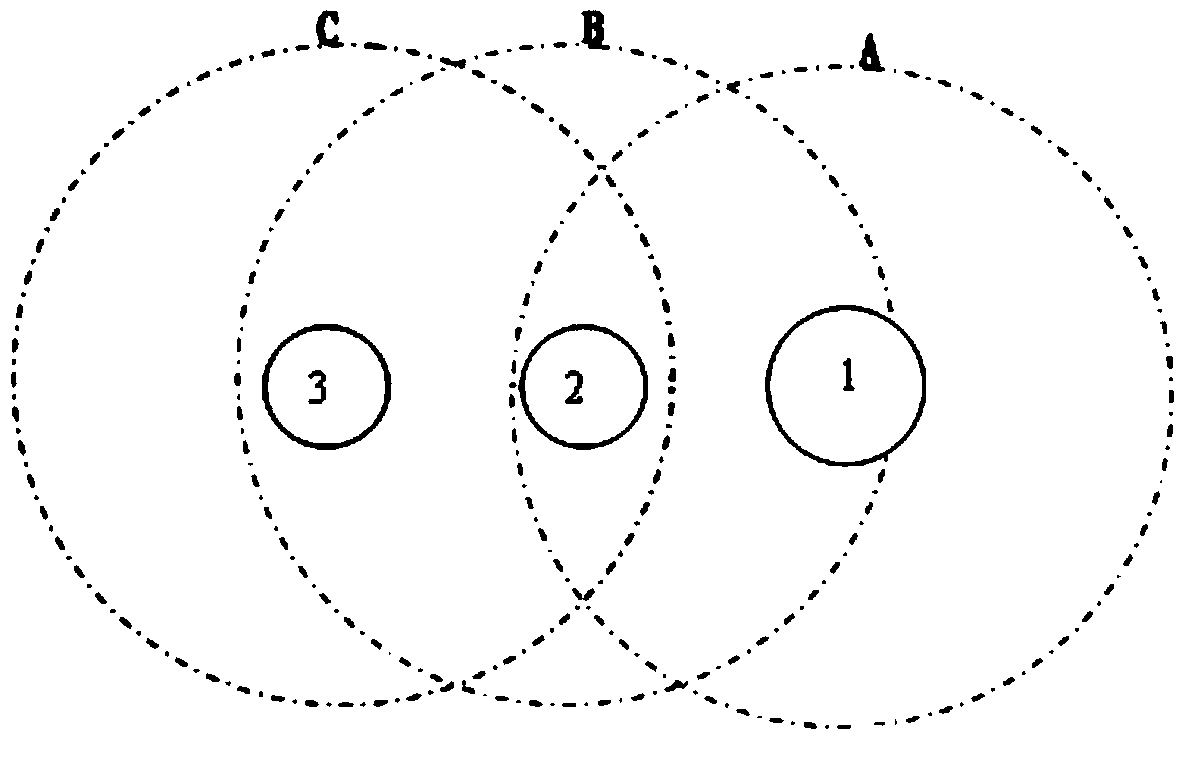
[0068] In the present invention, the reference station in the measurement system is the central node, the observation station is the sub-node, and the neighbor nodes of the central node (that is, the sub-nodes of the nodes that are located in the communication range of the central node and belong to the network to be grouped) are the first layer Child nodes, the neighbor nodes of the first layer of child nodes (that is, the child nodes that are located in the communication range of the first layer of child nodes and belong to the nodes of the network to ...


PUM


Abstract

The invention discloses a networking method in RTK measurement. According to the method, a base station is used as a center node, an observation station is used as a child node, a neighbor node of the center node is used as a first layer child node, a neighbor node of the first layer child node is used as a second layer child node, and the like; the child nodes of the layer with the small sequence number are relay nodes from the child nodes of the layer with the large sequence number to the center node; when networking is needed, a networking order and networking parameters are sent to the center node, and after receiving the networking order, the center node carries out active networking or passive networking according to the received networking parameters. According to the method, the observation station is used as a relay in the communication process, so that the theoretical measurement range is widened infinitely, then the emission power consumption of the base station is reduced, and the equipment cost is reduced.

Description

technical field [0001] The invention relates to the field of RTK measurement, in particular to a networking method in RTK measurement. Background technique [0002] RTK (Real-time kinematic, real-time differential positioning) is a measurement method that can obtain centimeter-level positioning accuracy in real time in the field. [0003] In the traditional RTK operation mode, the base station transmits its observation value and station coordinate information to the rover station through the data radio station. The rover station receives the data from the base station and collects GPS observation data for real-time processing. Get centimeter-level positioning results. [0004] like figure 1 As shown, it is a schematic diagram of the existing RTK measurement, 1 is the base station, 2 and 3 are the observation stations, and A, B and C are the effective transmission ranges of 1, 2 and 3 respectively. When the reference station 1 wants to communicate with the observation stat...

Claims


Application Information

Patent Timeline
Patent Type & Authority Applications(China)
IPC IPC(8): H04W16/18H04W24/00H04W40/32
CPCY02D30/70
Inventor 王春华刘阳
Owner HARXON CORP
Why Eureka
Try Eureka