
Object image shooting and splicing method

An image and object technology, applied in the field of shooting and stitching object images, can solve problems such as distortion, and achieve the effect of accurately stitching images

Inactive Publication Date: 2014-11-26
AISYS VISION CORP
View PDF3 Cites 10 Cited by
  • Summary
  • Abstract
  • Description
  • Claims
  • Application Information

AI Technical Summary

Problems solved by technology

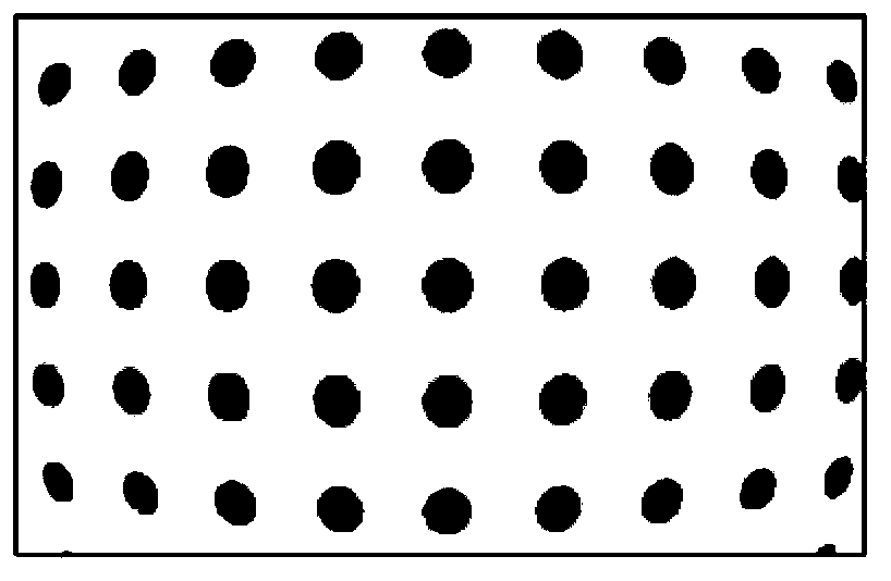
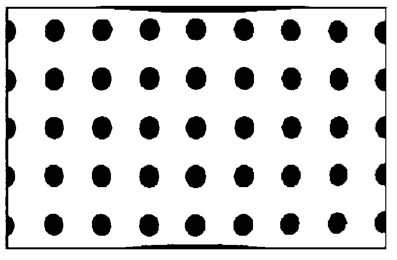
Depend on Figure 3C It can be clearly seen that the packaged chip images obtained after splicing have serious distortion problems

Method used


Image

  • Object image shooting and splicing method
  • Object image shooting and splicing method
  • Object image shooting and splicing method

Examples


Embodiment Construction

[0040] The invention provides a method for shooting and splicing object images. This method is to determine the real coordinates of the photographed object according to a real space coordinate system, and set different image coordinate systems for the images of different regions of the photographed object. Then, by finding the coordinate correspondence between each image coordinate system and the real space coordinate system, the relative positions among multiple images are determined. In this way, multiple images can be effectively spliced ​​and combined to obtain a complete image of the captured object.

[0041] Please refer to Figure 4 , which shows the flow of a method for shooting and stitching object images provided by the present invention.

[0042] First, step S01 is executed to set up multiple cameras above a working platform. Multiple cameras can be set up at different heights, and the lenses of the cameras can be adjusted separately to have different focal lengt...


PUM


Abstract

An object image shooting and splicing method comprises the following steps: disposing an object on a working platform; determining real coordinate of the object according to a real space coordinate system; respectively shooting different areas of the object to obtain a plurality of images; respectively setting an image coordinate system for each image; determining a coordinate corresponding relation between each image coordinate system and the real space coordinate system; determining a position relative relation among the plurality of images through the coordinate corresponding relation; splicing and combining the plurality of images according to the position relative relation. Compared with the technology in the prior art, through analyzing repeated parts in each image and splicing the image, the images can be spliced accurately through the method provided by the invention.

Description

technical field [0001] The present invention relates to a method for shooting and splicing images of objects, in particular to a method for splicing images by distinguishing the coordinate correspondence between real coordinates of objects and image coordinates of images captured by a camera. Background technique [0002] In today's industrial production process, image inspection systems are widely used in automated production lines for purposes such as object identification, automatic positioning, and size measurement to guide the robotic arm to process or manufacture components on the production platform program, or inspect whether the produced objects meet the high-precision requirements of size and appearance. [0003] In the known technology, in terms of configuration of the image inspection system, in addition to setting up a camera on the production line or on the machine tool table, aiming at the object to be inspected and shooting, there will also be another camera ...

Claims


Application Information

Patent Timeline
Patent Type & Authority Applications(China)
IPC IPC(8): H04N5/232G06T3/40G06T5/50
Inventor 李正道
Owner AISYS VISION CORP
Learn More