Automatic-locating continuous pushing device for large box beams

A technology of automatic positioning and jacking devices, applied in bridges, bridge construction, erection/assembly of bridges, etc., can solve the problems of long hoisting equipment period, increased construction cost, and restriction of jacking efficiency, so as to reduce potential safety hazards and save energy. Construction cost, the effect of increasing the pushing speed

Inactive Publication Date: 2014-11-26
CHINA RAILWAY 21TH BUREAU GROUP
View PDF6 Cites 5 Cited by
  • Summary
  • Abstract
  • Description
  • Claims
  • Application Information

AI Technical Summary

Problems solved by technology

Due to the heavy weight of the reaction seat and the ejector rod, when changing the position of the reaction seat or adding and removing the ejector rod on the pushing platform, a crane must be used for lifting and manual cooperation. The defo...

Method used


Image

  • Automatic-locating continuous pushing device for large box beams
  • Automatic-locating continuous pushing device for large box beams

Examples


Embodiment Construction

[0011] Below in conjunction with embodiment and accompanying drawing, the present invention is described in more detail;

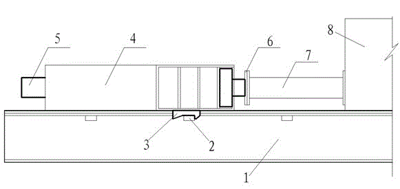
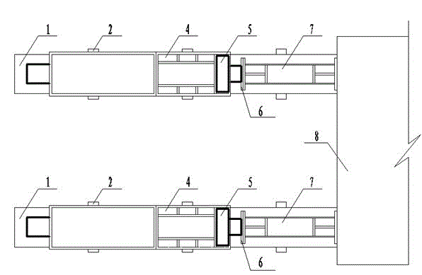
[0012] According to the length of the jacking stroke, three groups of wedge-shaped reaction seats (2) are symmetrically fixed and installed on the inner and outer sides of the double-track slideway (1) along the same distance and the same cross-section along the pushing direction, respectively, and are symmetrically fixed and installed on the lower part of the pushing bracket (4). The positioning slots (3), the positioning slots (3) are respectively engaged with the wedge-shaped reaction seat (2), the jacks (5) are respectively set in the pushing brackets (4), and the front ends of the jacks (5) are respectively passed through the flanges The disc (6) is fixedly connected to the rear end of the buffer ejector rod (7), and the front end of the buffer ejector rod (7) is respectively fixedly connected to the box beam (8).

[0013] When using the present inve...


PUM


Abstract

The invention discloses an automatic-locating continuous pushing device for large box beams. According to the technical scheme, a plurality of sets of wedge-shaped counter force bases are symmetrically and fixedly installed on the inner side and the outer side of a double-track sliding way respectively in the pushing direction at equal intervals and with the same section, locating clamping grooves are symmetrically and fixedly formed in the lower portions of a pushing support base and meshed with the wedge-shaped counter force bases respectively, jacks are installed inside the pushing support base in a sleeved mode, the front ends of ejection rods of the jacks are fixedly connected with the rear ends of buffering ejection rods through flange plates respectively, and the front ends of the buffering ejection rods are fixedly connected with the box beams respectively. The device overcomes the shortcomings of an existing device used for pushing construction, the positions of the counter force bases do not need to be replaced continuously or the ejection rods do not need to be added or reduced continuously, continuous pushing operation can be carried out, the pushing speed is increased greatly, automatic locating of a pushing system is achieved, the occupation time of hoisting equipment is shortened, the construction cost is saved, and the potential safety hazards on the site are reduced.

Description

technical field [0001] The invention relates to a large box girder jacking device, in particular to a large box girder continuous jacking device which can be automatically positioned and belongs to the field of road and bridge construction. Background technique [0002] With the rapid development of high-speed railway and expressway construction, how to safely and quickly cross the existing operating lines has become a common goal for researchers to explore and study. At present, crossing special obstacles such as existing railways, highways, and valleys Cantilevered or swivel concrete beams are used, but since cantilevered or swiveled concrete beams have high requirements for on-site construction conditions, for engineering projects that cross special obstacles with difficult construction site conditions and high safety risk levels, it is better to use jacking construction. A relatively safe and efficient construction technology. [0003] The jacking construction is to ap...

Claims


Application Information

Patent Timeline
IPC IPC(8): E01D21/06
Inventor 高玉峰唐海波赖林
Owner CHINA RAILWAY 21TH BUREAU GROUP
Why Eureka
Try Eureka