Anti-reflux intravenous indwelling needle

A venous indwelling needle and anti-reverse flow technology, applied in the field of medical indwelling needles, can solve the problems of easy cracking, single function, easy damage of the extension tube, etc., and achieve the effect of convenient blood drawing

Active Publication Date: 2017-10-03
丁培琪
View PDF9 Cites 0 Cited by
  • Summary
  • Abstract
  • Description
  • Claims
  • Application Information

AI Technical Summary

Problems solved by technology

[0007] In view of the above-mentioned various shortcomings of the existing indwelling needles, the purpose of the present invention is to provide a new type of anti-reflux venous indwelling needle, which is used to solve the problems of easy cracking of the outer needle seat of the existing indwelling needles, single function, and easy extension of the tube. Damage, easy to cause skin allergies and other problems

Method used


Image

  • Anti-reflux intravenous indwelling needle
  • Anti-reflux intravenous indwelling needle
  • Anti-reflux intravenous indwelling needle

Examples


Embodiment 1

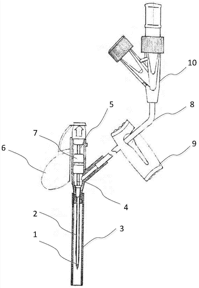
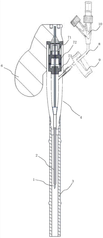
[0025] see below first figure 2 The first embodiment of the present invention will be described. To simplify the description, figure 2 neutralize figure 1 The same marks are used for the same or corresponding parts of the existing indwelling needles in function or structure.
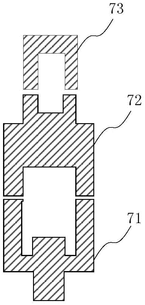
[0026] According to the idea of ​​the present invention, figure 2 In the preferred embodiment shown, the isolation assembly 7 has adopted less hardness of silica gel, and further includes three parts of components 71, 72 and 73 (see image 3 magnified view of the ). More preferably, the components 71, 72 and 73 in this example are all made in the shape of a bowl - having a cavity, and are arranged according to figure 2 (and image 3 ) shown in the arrangement: the "bowl mouth" of the assembly 71 (that is, the open end of the cavity) faces the tail of the inner needle 1, and the "bottom of the bowl" (that is, the closed end of the cavity) faces the direction of the needle tip of the inner needle...

Embodiment 2

[0031] see below Figure 7 The second embodiment of the present invention will be described. Figure 7 In the embodiment, the isolation assembly 7 is the same as that in embodiment 1, so it is not repeated here. Figure 7In the second embodiment, the outer needle seat 4 includes an elastic needle seat 41 and a three-way pipe 42 , and a one-way valve 12 is provided between the elastic needle seat 41 and the three-way pipe 42 . The one-way valve 12 can only be guided from top to bottom in the figure. Like this, on the one hand, after the inner needle 1 enters the vein together with the outer needle tube 2, the venous blood return is blocked in the blood return cavity (at the opening of the one-way valve) 14, preventing Excessive blood return; on the other hand, the operator can observe the venous blood return through the blood return chamber 14 to judge whether the inner needle 1 and the outer needle tube 2 have entered the vein, without having to observe the blood return in th...


PUM


Abstract

The invention provides a novel reverse-flowing-prevention venous indwelling needle. The needle comprises an inner needle, an outer needle tube, an extension hose, a water-stopping clamp and an outer needle base. The inner needle is made of hard material and is provided with a blood returning groove, and the tail of the inner needle is connected with a puncturing needle base. One end of the extension hose is connected with a liquid injecting connector assembly, and the water stopping clamp is located outside the extension hose and used for controlling on-off of the extension hose. The first end of the outer needle base comprises a through hole, the second end of the outer needle base is connected with the other end of the extension hose, and the third end of the outer needle base comprises a seal part, and the seal part comprises an isolation combined part. The isolation combined part comprises two or more components. According to the novel reverse-flowing-prevention venous indwelling needle, because an isolation plug made of rubber silicon material is used, the risk of fracturing the outer needle rear base through propping is avoided; after being pulled out, the inner needle can puncture into the vein again through the isolation plug, intravenous dripping is achieved, and besides various operations such as blood drawing and pressure testing are convenient to perform.

Description

technical field [0001] The invention relates to a medical indwelling needle, in particular to an anti-reflux venous indwelling needle. Background technique [0002] Intravenous infusion is widely used in clinical practice, but each intravenous infusion requires skin puncture. For patients who need long-term infusion, it not only increases the suffering of patients, increases the workload of nurses, but also causes greater infection risk. [0003] In order to solve these problems, indwelling needles are often used clinically for patients who need long-term infusion and critically ill patients, and multiple infusions can be performed after one puncture. The structure of existing venous indwelling needle or anti-reflux venous indwelling needle is as attached figure 1 As shown, it generally includes an inner needle 1, an outer needle tube 2, a sheath 3, a Y-shaped outer needle seat 4, a puncture needle seat 6, an isolation plug 7, a water stop clip 9, and an infusion tee tube ...

Claims


Application Information

Patent Timeline
Patent Type & Authority Patents(China)
IPC IPC(8): A61M5/158A61M5/36
Inventor 丁培琪邓智光
Owner 丁培琪
Why Eureka
Try Eureka