Manufacturing method for adjustable capacitor and adjustable capacitor
A manufacturing method and capacitor technology, applied in the field of automobiles, can solve the problems that capacitors cannot be applied to the performance test of automobile engine ignition coils, etc., and achieve the effects of wide range of capacitance adjustment, simple operation, and meeting the requirements of adjustment accuracy
- Summary
- Abstract
- Description
- Claims
- Application Information
AI Technical Summary
Problems solved by technology
Method used
Image
Examples
Embodiment 1
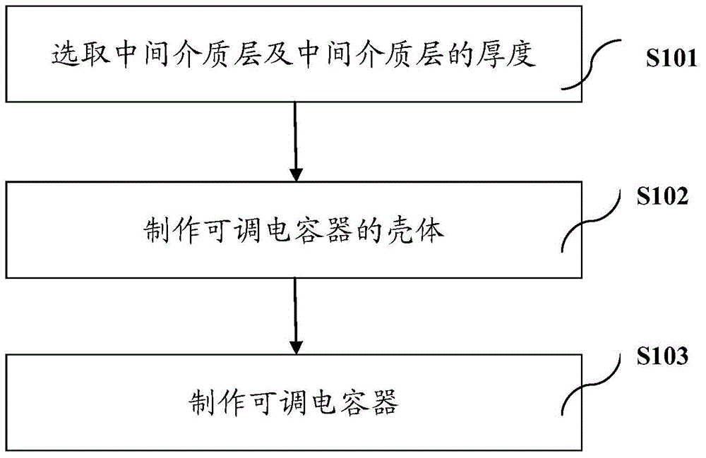
[0062] In step S101,
[0063] Select the intermediate dielectric layer and the thickness of the intermediate dielectric layer:
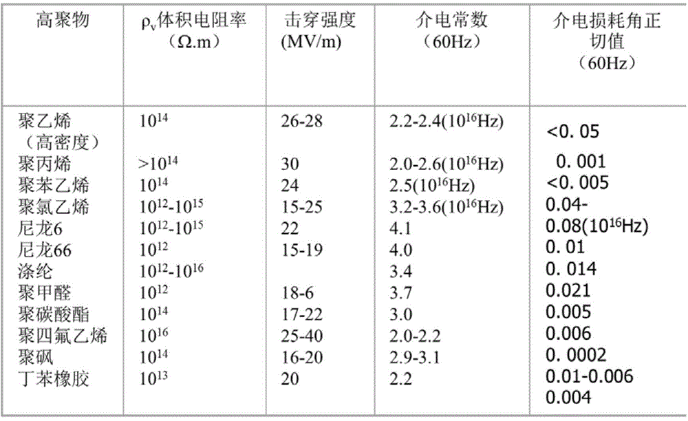
[0064] Some commonly used polymers used as intermediate dielectric layers and some parameters of polymers such as image 3 As shown, since there are many types of polymers commonly used, here, the image 3 Take nylon 66 as an example:
[0065] Depend on image 3 It can be seen from the parameters of nylon 66 in the figure that the breakdown strength of nylon 66 ranges from (15 to 19) MV / m. Due to differences in the manufacturing process, the breakdown strength of the same material will also vary. Therefore, when calculating the thickness of the intermediate dielectric layer, the lowest value of the intermediate dielectric layer is usually selected to ensure the safety of the adjustable capacitor. Set the measured voltage of the adjustable capacitor to 40KV, the breakdown strength of nylon 66 is 15MV / m, according to the voltage measurement formula...
Embodiment 2
[0071] In step S102 and step S103:
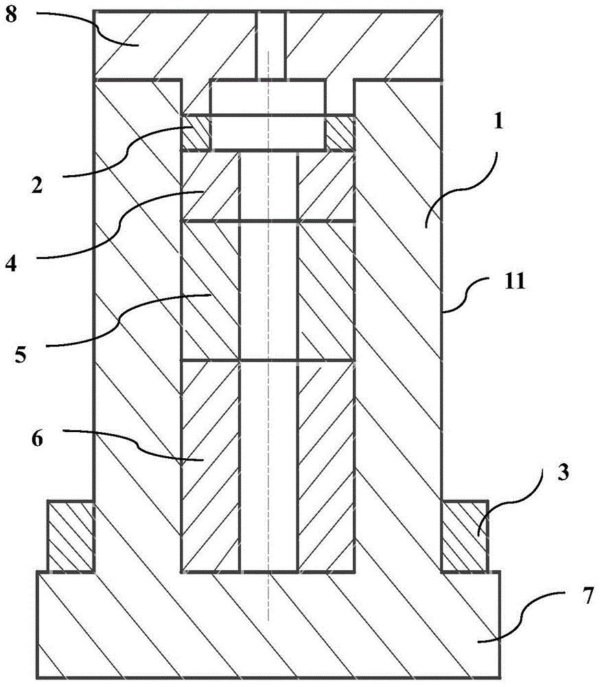
[0072] The intermediate dielectric layer is machined to form a hollow cylinder with one end open and the other end closed with a suitable radius, the inner polar plate is placed in the intermediate dielectric layer, and the outer polar plate is screwed to the outer surface of the intermediate dielectric layer.
[0073] The capacitance calculation formula for cylindrical capacitors is:
[0074] C 0 = 2 πϵl ln R B R A - - - ( 2 )
[0075] in,
[0076] C 0 is the capacitance generated between the inner pole plate and the outer pole plate, in this embodiment, C 0 is the capacitance generated between the inner an...
Embodiment 3
[0102] In step S102 and step S103:
[0103] According to the capacitance value C between the inner plate and the outer plate 0 , the thickness of the intermediate dielectric layer d, and formula (3), the preliminary determination of R A and R B , R A and R B cannot be selected too small or too large when R A and R B Too small, the capacitance value is too small; when R A and R B When it is too large, it is inconvenient to operate. R A with R B After determination, the length l of the pole plate can be obtained according to formula (2). Then C can be inversely calculated according to (4) 内 , C 外 , to obtain the adjustment range of the capacitance value. If there is a gap between the adjustment range of the obtained capacitance value and the target range, R can be adjusted according to the deviation of the result A and R B , and repeat this process until the target range of capacitance is obtained.
[0104] Thus, when R A , R B , l After confirmation, the heigh...
PUM
 Abstract
Description
Claims
Application Information
 - Generate Ideas
- Intellectual Property
- Life Sciences
- Materials
- Tech Scout
- Unparalleled Data Quality
- Higher Quality Content
- 60% Fewer Hallucinations
Browse by: Latest US Patents, China's latest patents, Technical Efficacy Thesaurus, Application Domain, Technology Topic, Popular Technical Reports.
© 2025 PatSnap. All rights reserved.Legal|Privacy policy|Modern Slavery Act Transparency Statement|Sitemap|About US| Contact US: help@patsnap.com


