
Electric bus charging pile safety protection system and use method in working process thereof

A technology for electric bus and car charging piles, which is applied in the direction of electric transmission signal systems, illuminated signs, instruments, etc., can solve the problems of being unable to predict the completion of the charging process from a long distance, unable to prompt information prompts, and inconvenient

Inactive Publication Date: 2014-11-19
张远镇 +1
View PDF9 Cites 1 Cited by
  • Summary
  • Abstract
  • Description
  • Claims
  • Application Information

AI Technical Summary

Problems solved by technology

[0007] Fourth, there is only one kind of warning symbol LED display on the warning sign. After the charging is completed, the message "safe" cannot be prompted, and the staff cannot predict the completion of the charging process from a distance, which is very inconvenient.

Method used

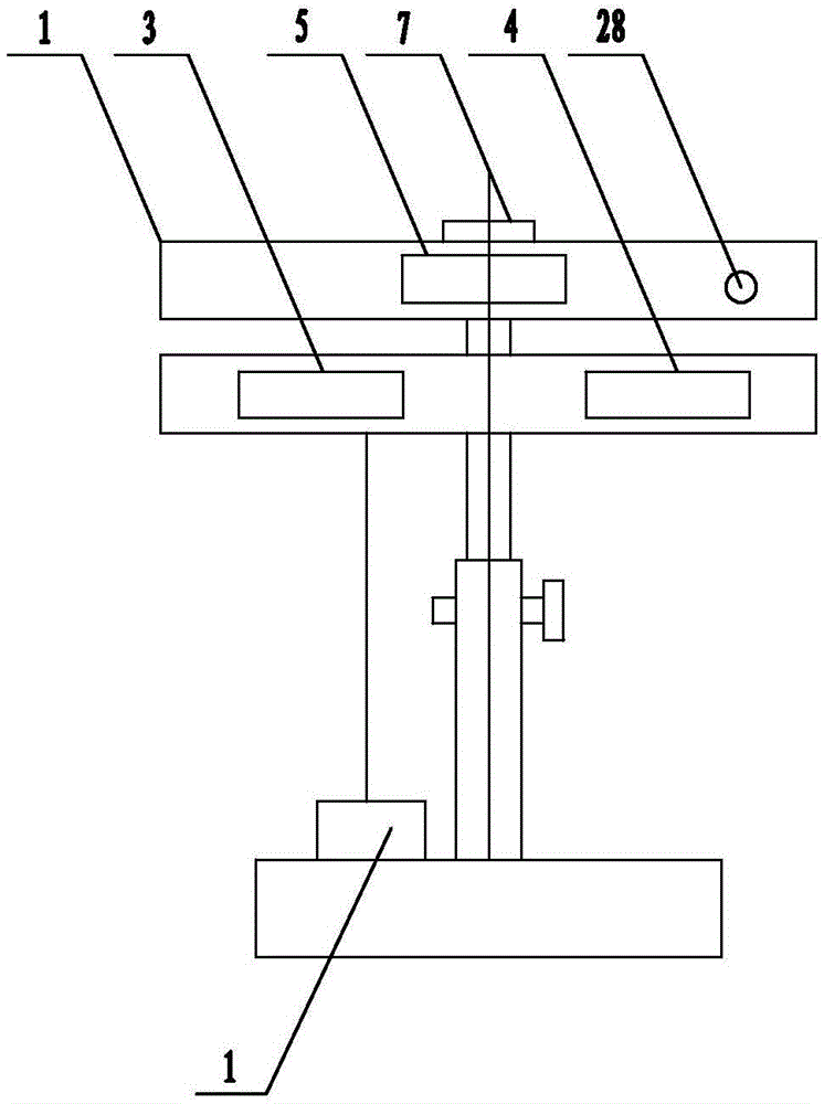
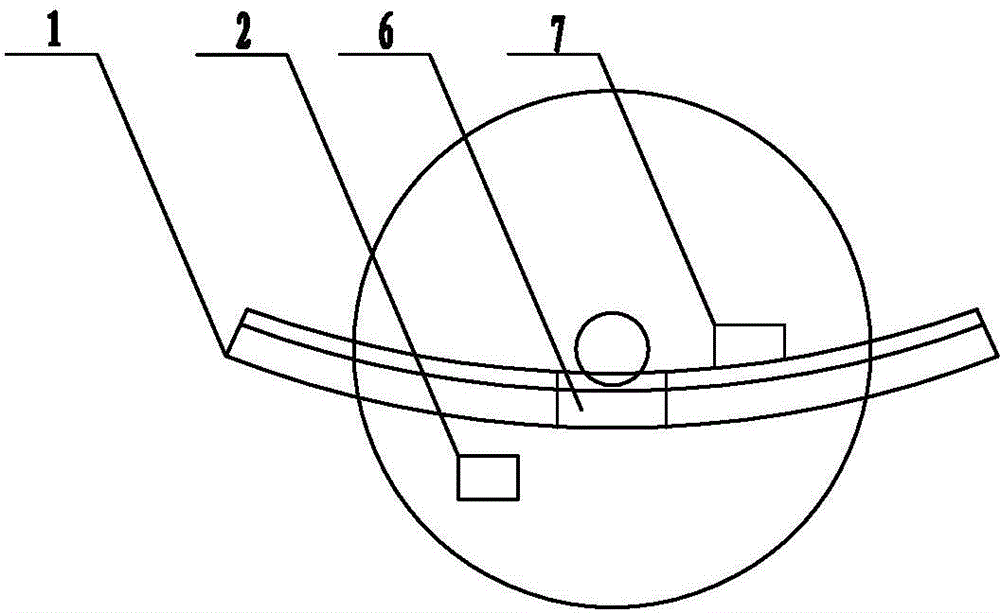
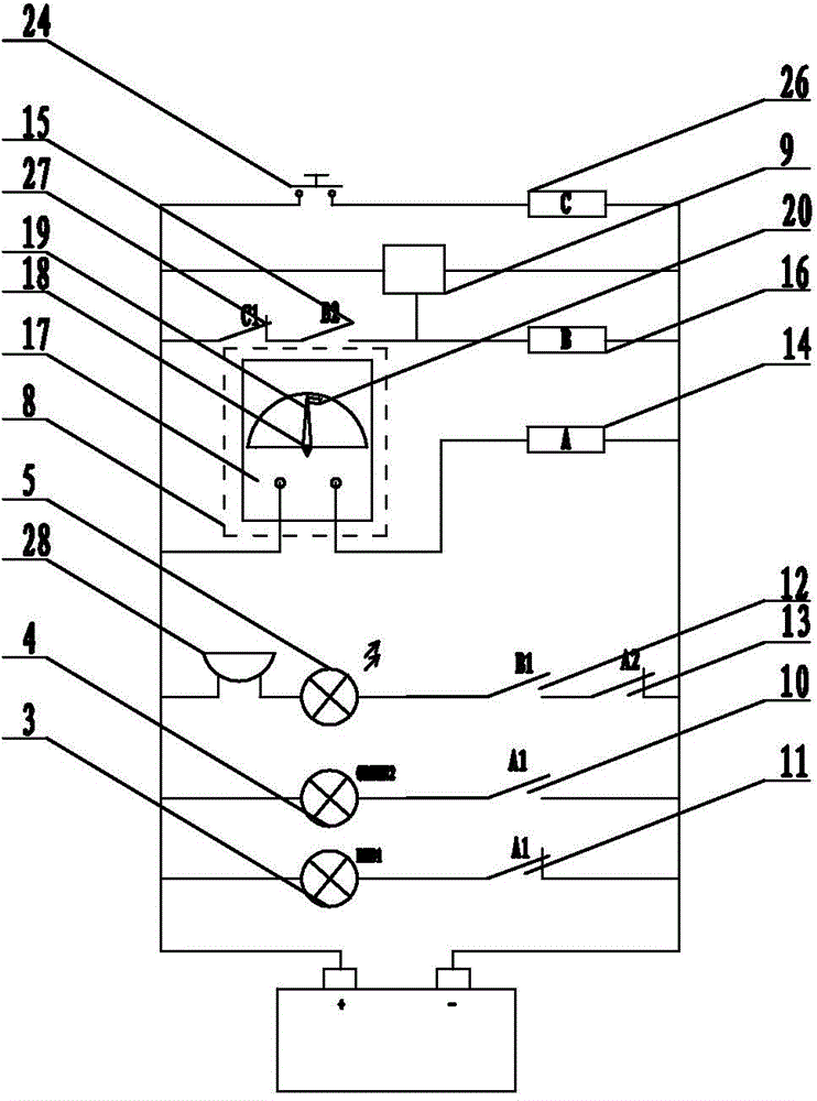

Image

  • Electric bus charging pile safety protection system and use method in working process thereof
  • Electric bus charging pile safety protection system and use method in working process thereof
  • Electric bus charging pile safety protection system and use method in working process thereof

Examples


Embodiment 1

[0040] Embodiment 1: as figure 1 and figure 2 As shown, the electric bus charging pile safety protection system described in the present invention includes an electric bus charging bay charging safety protection device, and the electric bus charging bay charging safety protection device is provided with a warning sign 1 and a storage battery 2, and the warning sign 1 There is a warning sign 3 composed of LED lights on the front surface, the battery 2 is connected to the charging power supply, the warning sign 1 is arc-shaped, and the warning sign 1 is equipped with warning signs B4, warning signs C5 and piezoelectric ultrasonic generator on the front surface 6. An alarm circuit 7 is provided on the rear surface of the warning sign 1, and the warning sign 3, the warning sign B4 and the warning sign C5 are connected to the positive and negative poles of the storage battery 2 through the warning circuit 7.

Embodiment 2

[0041] Embodiment 2: On the basis of the structure described in Embodiment 1, the alarm circuit 7 includes a current detection device 8, a sound wave receiver 9, a relay A, a relay B and an alarm 28, and the warning sign 3 and the warning sign B4 are connected with the relay A respectively. A normally open contact 10 of the relay A and a normally closed contact 11 of the relay A are connected in series on the positive and negative poles of the battery 2, the alarm 28, the warning symbol C5, a normally open contact 12 of the relay B and another normally open contact of the relay A The closed contact 13 is connected in series to form a series circuit 2, the current detection device 8 and the coil 14 of the relay A are connected in series to form a series circuit 3, the other normally open contact 15 of the relay B is connected in series with the coil 16 of the relay B to form a series circuit 4, and the series circuit 2. The two ends of the two power terminals of the series circu...

Embodiment 3

[0042] Embodiment 3: on the basis of the structure described in embodiment 2, as image 3As shown, the current detection device 8 includes an ammeter 17, the ammeter 17 is provided with a metal rotating shaft 18 and a metal pointer 19, the dial is provided with a contact 20, and the ammeter 17 is provided with two signal terminals, one end of which is respectively connected to to the metal rotating shaft 18 and the contact 20, and the other end is respectively connected to the battery 2 and the coil 14 of the relay A. The contact 20 is arc-shaped, and the arc is adapted to the dial. The two ends of the contact 20 correspond to "0A" on the dial respectively. " scale and "5A" scale.


PUM


Abstract

The invention provides an electric bus charging pile safety protection system and a use method in the working process thereof, and belongs to the field of electric bus charging pile safety protection devices. The electric bus charging pile safety protection system comprises an electric bus charging bin opening charging safety protection device. The electric bus charging bin opening charging safety protection device is provided with a warning board and a storage battery. A warning symbol composed of LED lamps is arranged on the front surface of the warning board. The storage battery is connected to a charging power source. The warning board is of an arc shape, a warning symbol B, a warning symbol C and a piezoelectric ultrasonic generator are further arranged on the front surface of the warning board, a warning circuit is arranged on the rear surface of the warning board, and the warning symbol, the warning symbol B and the warning symbol C are connected to the positive electrode and the negative electrode of the storage battery through the warning circuit. Car paint can not be scratched; any objects which may have the electric shock hazard can be prevented from getting close to the electric bus charging pile safety protection system, and the electric bus charging pile safety protection system is reliable; the service life of the LED lamps is long; after charging is completed, automatic safety prompting can be provided.

Description

technical field [0001] The invention provides a safety protection system for a charging pile of an electric bus and a use method thereof in a working process, belonging to the field of safety protection devices for a charging pile of an electric bus. Background technique [0002] During the charging process of the electric bus, the charging plug on the charging gun is inserted into the vehicle socket of the electric bus for charging. Because the charging current is too large, if a non-staff member pulls out the charging gun, arcing will occur. It is very easy to cause the danger of electric shock. The existing electric bus charging bay charging safety protection device only passively prompts the non-staff through the warning symbols composed of LED lights, and uses the battery to supply power to the non-staff. Leave after seeing the warning sign of the warning symbol to avoid electric shock. [0003] Current prior art defect is: [0004] First, the warning board of the cha...

Claims


Application Information

Patent Timeline
IPC IPC(8): G09F13/22G08B7/06
Inventor 张传坤张远镇刘荫琦刘仕栋房明赵舒铭杨跃宇房军李彤梅田茂林王明剑刘东明李萍
Owner 张远镇
Learn More